PASCO Florian
Hi there! 
🎓 I’m Florian Pasco, a Master’s student in Engineering specializing in Electronics, Computer Science, and Mechatronics.
👨💻 I am passionate about creating and sharing open-source projects that are reusable and easy to understand, helping others grow in the fields of electronics, programming, and mechanics.
🔧 Recently, I developed a full-stack project using React, Next.js, Django, Python, and PostgreSQL, showcasing my skills in modern web and backend development.
📚 Beyond technology, I enjoy self-training, exploring personal development, and learning from resources like the French Polar Institute.
⛺ I love traveling and discovering new places—whether it’s hiking, biking, or going on road trips in my car!
🎯 I’ve also applied my skills in reverse engineering, successfully diagnosing and repairing 20+ electronic units. Additionally, I designed and worked on a thermal resistance control board with feedback from a thermal resistance sensor for precise regulation.
BMWInternReport2025
🚗 EV charger testing & teardown
BMWInternReport2025 documents my internship at BMW Group as an Electronics Engineer Intern. The internship focuses on benchmarking, reverse engineering, and performance analysis of AC wall-mounted electric vehicle chargers. Tasks include hardware teardown, embedded firmware analysis, reparability assessments, and systems-level testing of smart charging features.
🎯 Purpose
- 🔍 Benchmarking: Technical evaluation of commercial EV chargers through standardized test procedures.
- 🔄 Reverse Engineering: Disassembly and analysis of internal hardware and firmware components.
- ⚡ Performance Testing: Electrical load testing and functional verification under real-world conditions.
- 🌐 Smart Feature Analysis: Assessment of connected functionalities like Wi-Fi, load scheduling, and app integration.
- 📊 Comparative Analysis: Development of comparison matrices and reparability indices to guide design improvements.
📝 Internship Highlights
| 🏷️ Task | 🔍 Description |
|---|---|
| 🔧 Hardware Teardown | Disassembled PCBs, power electronics, and embedded systems for component-level analysis. |
| 🔄 Reverse Engineering | Used tools such as BoardMapper to map circuit topology and identify system architecture. |
| ⚡ Electrical Testing | Conducted current and power measurements under load to validate performance claims. |
| 📱 Smart Feature Testing | Evaluated app-based controls, load management, and renewable integration capabilities. |
| 📊 Benchmark Development | Created comparison charts and indices evaluating both hardware and software features. |
📍 Internship Details
| Item | Description |
|---|---|
| Company | BMW Group |
| Role | Electronics Engineer Intern |
| Duration | July 2025 – Present (Ongoing) |
| Location | Munich, Bavaria, Germany (On-site) |
BatteryLevelIndicator
🔋 Battery status with LED display!
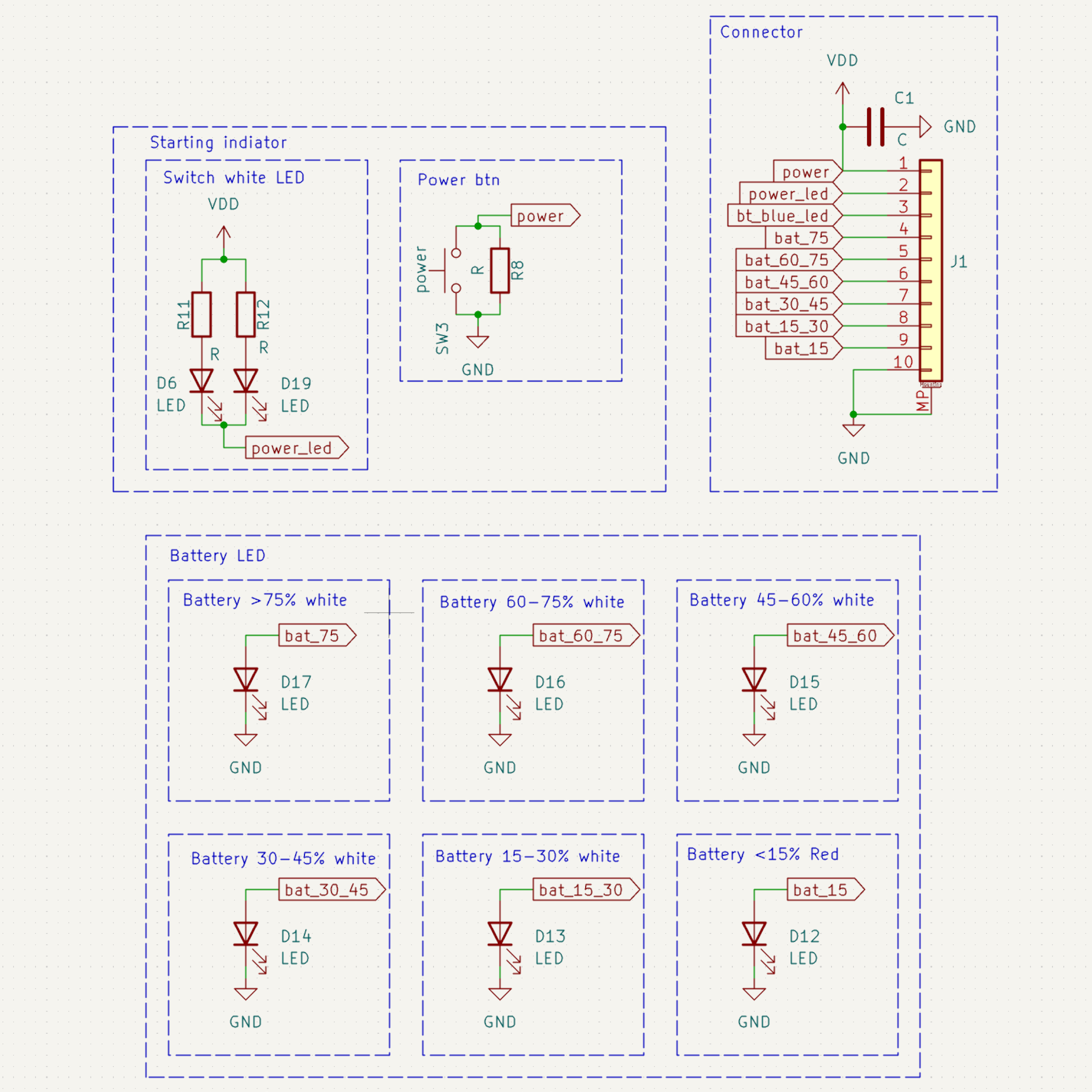
The Battery Level Indicator is an open-source project designed to visually display the charge level of a battery using five green LEDs and a sixth red LED for critical low levels. The board also features an ON/OFF button that activates the system, illuminating two white LEDs when turned on and two blue LEDs at other times.
🎯 Purpose
- 🔋 Battery Monitoring: Provides an intuitive LED-based display of battery charge levels.
- 🔘 Power Control: Includes an ON/OFF switch for system activation.
- 🌟 User-Friendly: Simple and effective visual indicators for battery status.
- 🛠️ Open-source & Customizable: Modify and adapt for various battery-powered projects.
📝 Features
| 🏷️ Feature | 🔍 Description |
|---|---|
| 🔋 Battery Level Indication | 5 green LEDs indicate battery charge level |
| 🚨 Low Battery Warning | 1 red LED lights up when the battery is critically low |
| 🔘 Power Switch | ON/OFF button for system control |
| 💡 ON Indicator | 2 white LEDs light up when the system is ON |
| 🔵 Standby Indicator | 2 blue LEDs light up in other situations |
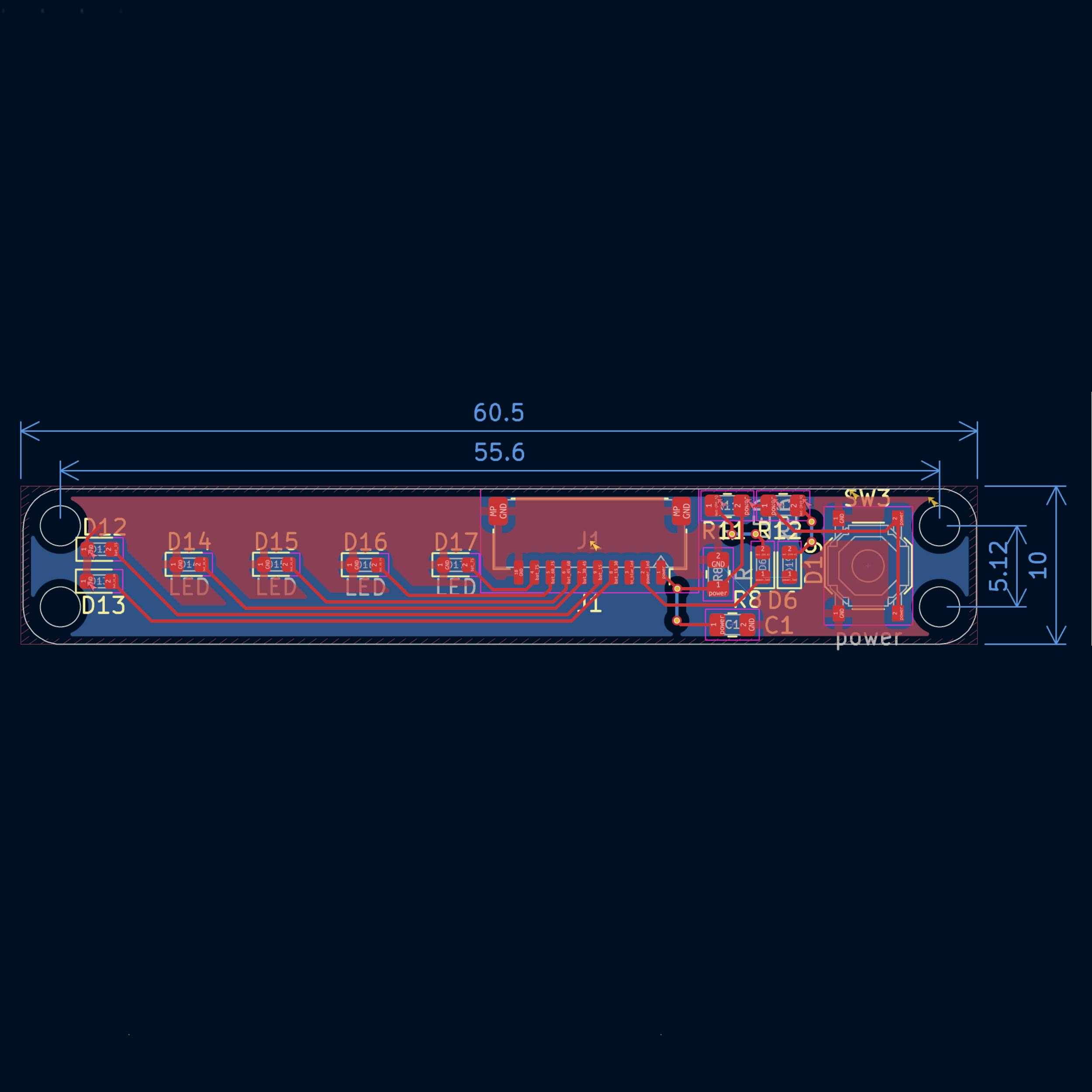
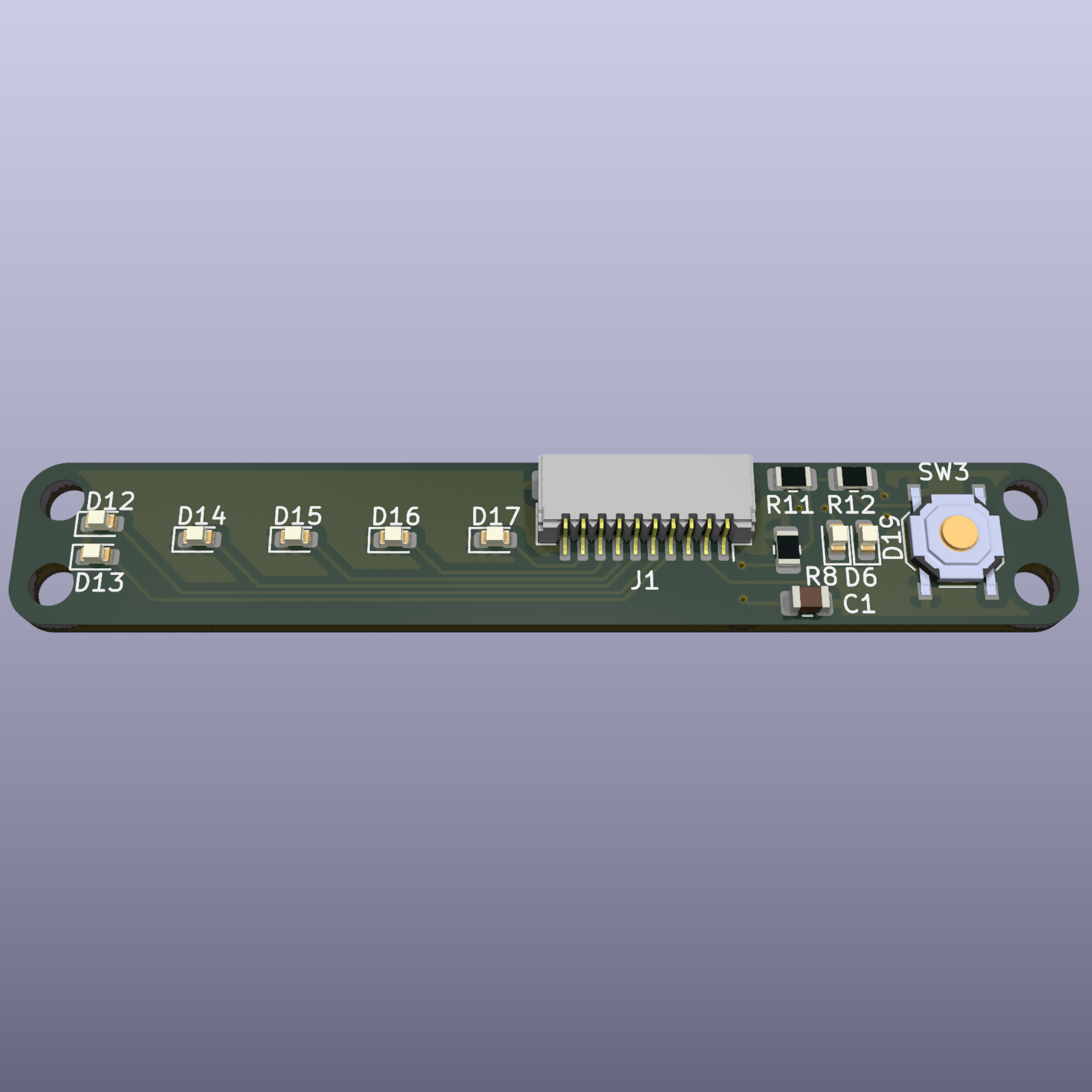
| 🖥️ PCB Design | Open-source & customizable |
| 🌍 Use Cases | Battery-powered devices, embedded systems, and monitoring applications |
📐 PCB Design Preview
| 📜 Schematic | 🖥️ PCB Layout | 🏗️ 3D |
|---|---|---|
 |
 |
 |
BluetoothSpeakerKeyboard
🎛️ Minimalist PCB for speaker control
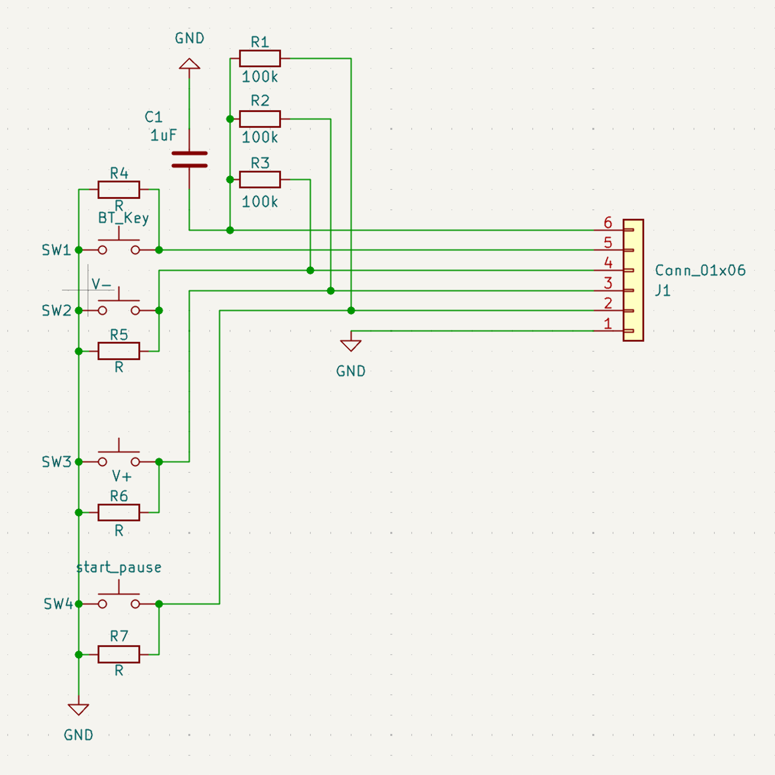
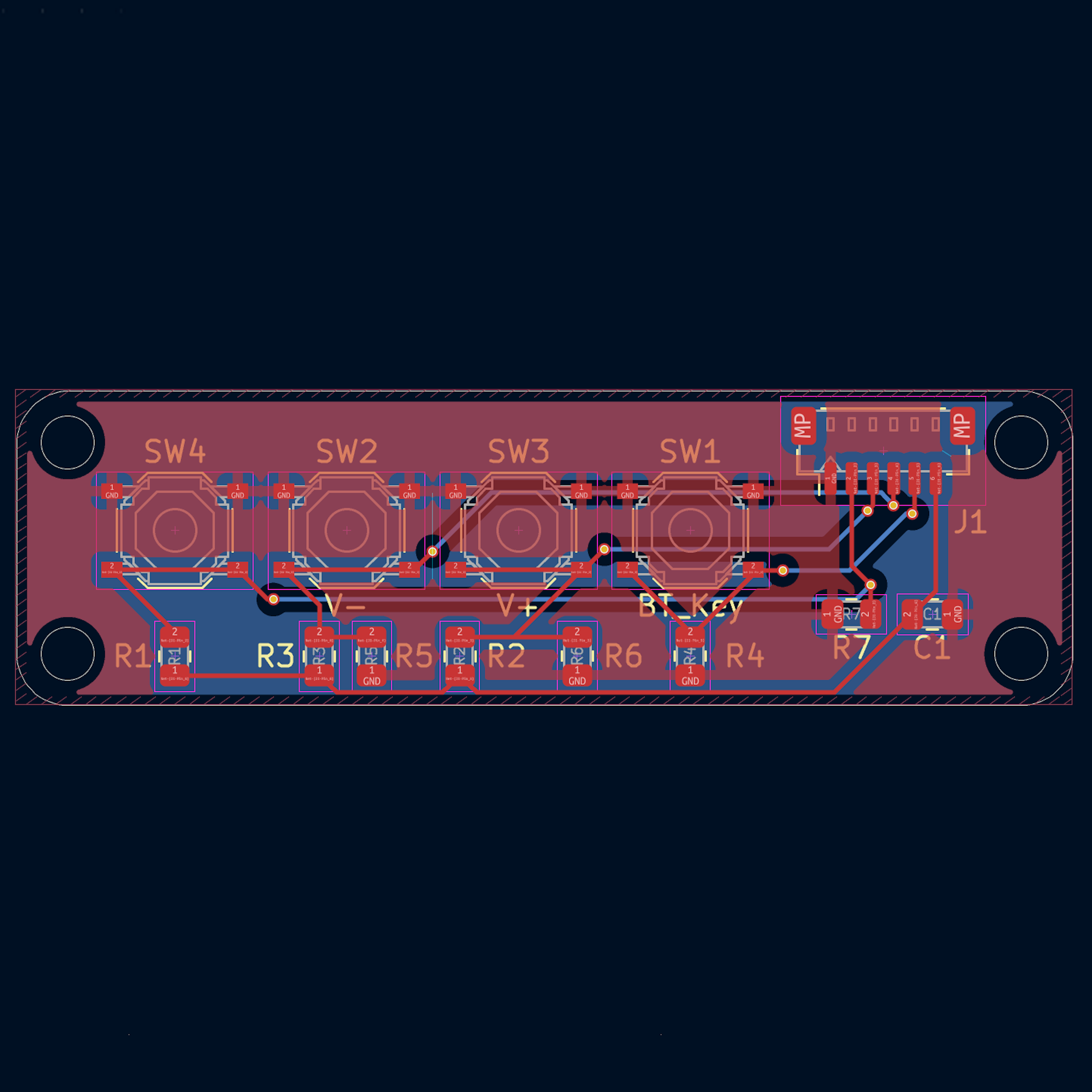
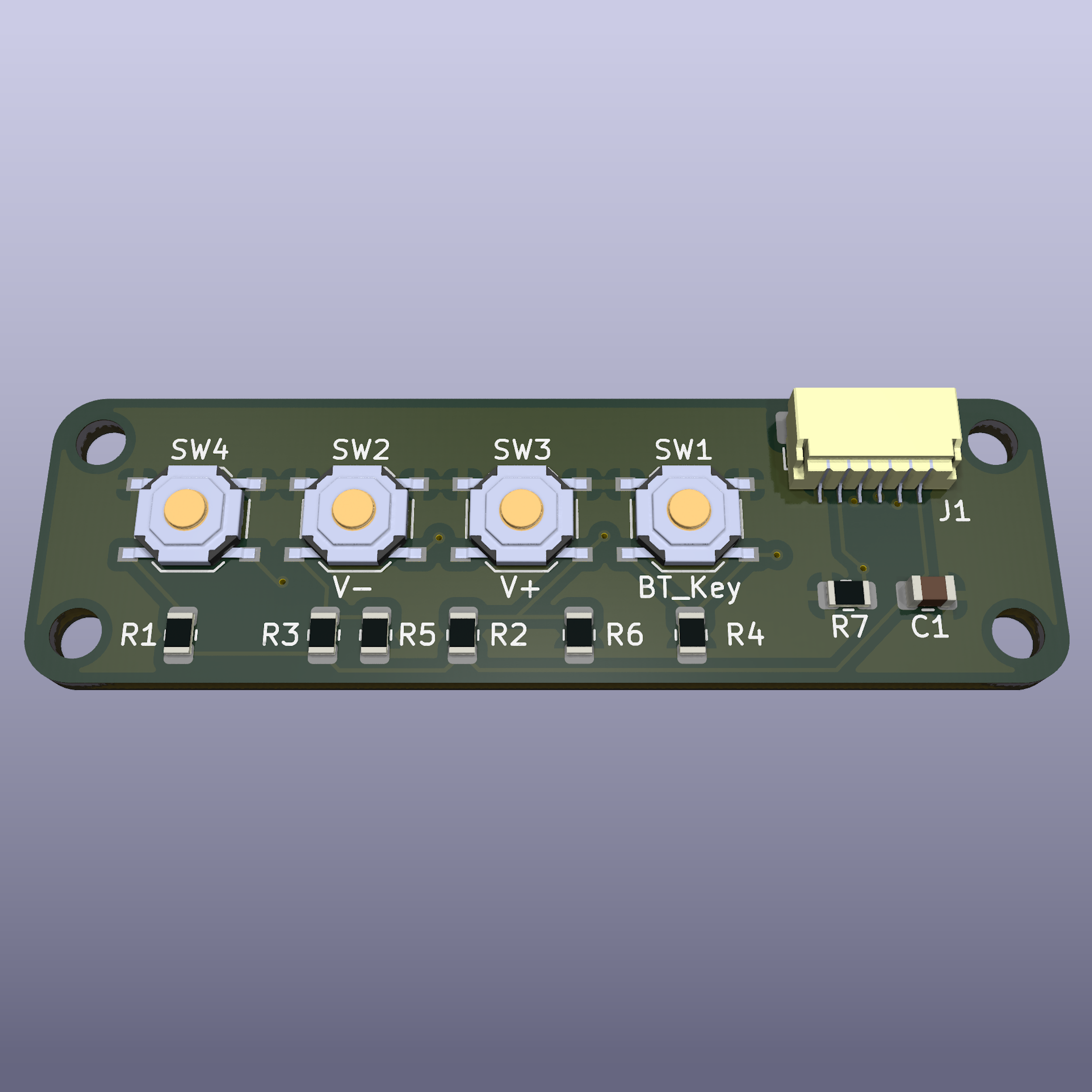
Bluetooth Speaker Keyboard is a minimalistic open-source PCB designed to provide simple control functionalities for Bluetooth speakers. The board features essential buttons for volume control, Bluetooth pairing, and play/pause functionality. It follows the Adafruit-compatible footprint, making it easy to integrate into existing projects.
🎯 Purpose
- 🔊 Seamless audio control: Easily manage volume, pairing, and playback.
- 🎛️ Compact and efficient: Designed for integration with Bluetooth speaker systems.
- 🛠️ Open-source and customizable: Modify the design to fit your specific needs.
- 🔌 Adafruit-compatible: Fits within Adafruit’s standard PCB footprint for easy use in DIY projects.
📝 Features
| 🏷️ Feature | 🔍 Description |
|---|---|
| 🔉 Volume Control | Adjust the speaker’s volume up and down |
| 🔄 Play/Pause Button | Start or stop the music playback |
| 🔵 Bluetooth Pairing Button | Activate pairing mode for easy device connection |
| 🔧 Minimalist Design | Only essential components for simplicity |
| 🖥️ PCB Design | Open-source & customizable |
| 🌍 Use Cases | Embedded in DIY Bluetooth speakers, home automation systems |
| 🔌 Adafruit-Compatible | Follows Adafruit’s standard PCB footprint |
📐 PCB Design Preview
| 📜 Schematic | 🖥️ PCB Layout | 🏗️ 3D |
|---|---|---|
 |
 |
 |
BreizelecInternReport2024
🚜 Electronics diagnostics & repair in agriculture
BreizelecInternReport2025 contains the detailed internship report documenting my work as an Assistant Electronics Engineer Intern at Breizelec. The internship focused on diagnostics and reverse engineering of electronic systems in agricultural machinery, including hands-on troubleshooting, circuit repair, and test bench development.
🎯 Purpose
- 🔍 Diagnostics: In-depth fault investigation using diagnostic tools to identify electronic system failures.
- 🔄 Reverse Engineering: Development of functional schematics from electronic control units (ECUs).
- 🛠️ Circuit Repairs: Component-level PCB repair and rework of defective elements.
- ⚙️ Test Bench Design: Creation of custom Arduino-based CAN bus simulators for system validation.
- 📋 Technical Documentation: Comprehensive reporting of repair procedures and failure analysis.
📝 Internship Highlights
| 🏷️ Task | 🔍 Description |
|---|---|
| 🔧 Fault Investigation | Used diagnostic tools and error codes to identify root causes of system faults. |
| 🔄 Reverse Engineering | Analyzed ECUs to generate schematics and understand embedded system behavior. |
| 🛠️ PCB Repair | Executed component replacement and PCB rework to restore functionality. |
| 🛠️ Test Bench Development | Designed Arduino-based CAN bus simulators to replicate real operating conditions. |
| 📋 Reporting | Produced detailed technical reports on repairs and recurring failure modes. |
📍 Internship Details
| Item | Description |
|---|---|
| Company | Breizelec |
| Role | Assistant Electronics Engineer Intern |
| Duration | July 2024 – January 2025 (7 months) |
| Location | Châteaulin, Bretagne, France (On-site) |
D1R32InterfaceShield
🔌 Modular JST Shield D1R32
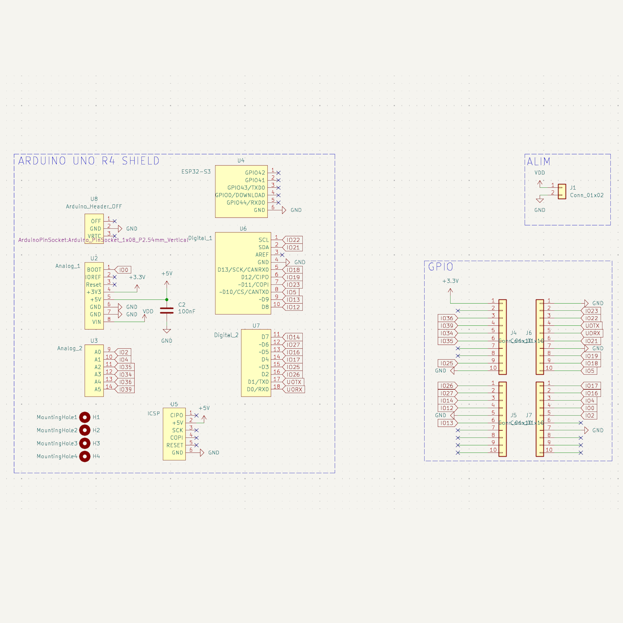
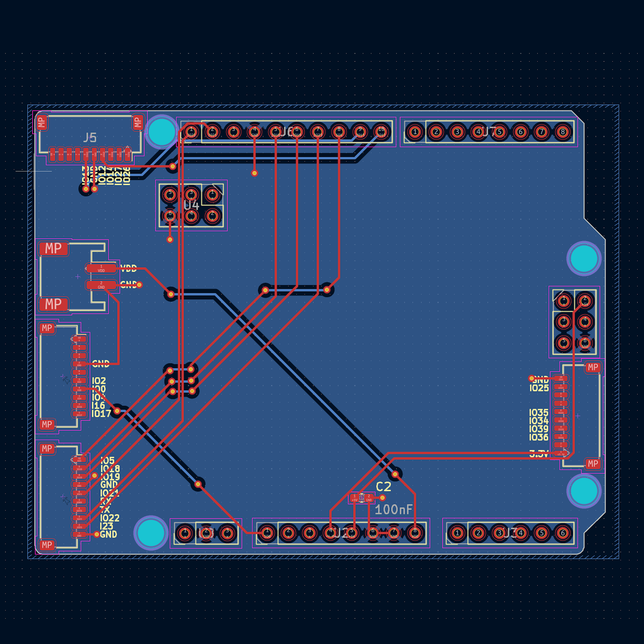
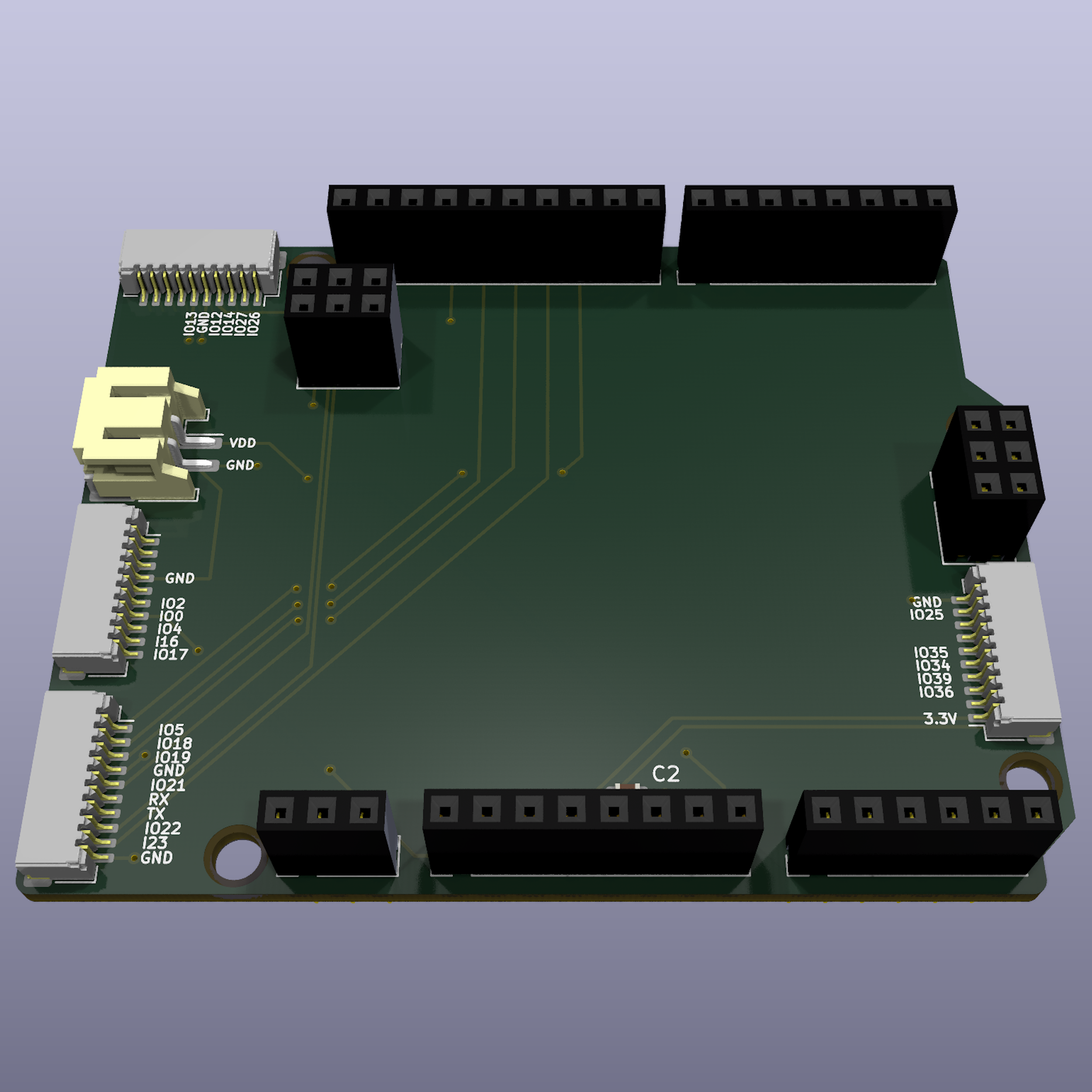
D1R32InterfaceShield is an open-source PCB that provides a reliable, modular interface between the UNO D1 R32 Board Module and various external modules via JST-SM & JST-SH connectors. It simplifies integration for IoT, automation, and embedded applications.
🎯 Purpose
- 🔌 Modular Interface: Bridges the UNO D1 R32 with sensors, actuators, and peripherals.
- 📏 Compact Design: Optimized layout for small enclosures and prototypes.
- 🛠️ Open-source Hardware: Fully customizable to match your project requirements.
📝 Features
| 🏷️ Feature | 🔍 Description |
|---|---|
| 🔌 Board Compatibility | Fits the UNO D1 R32 Board Module |
| 📡 Connectors | JST-SM & JST-SH for quick, secure connections |
| ⚡ Power Handling | Supports 3.3V and 5V logic |
| 🛠️ GPIO Access | Breaks out key digital and analog pins for peripherals |
| 🔧 Stability Components | Includes capacitors for signal conditioning |
| 🖥️ PCB Design | Open-source and easy to modify |
| 🌍 Use Cases | IoT, automation, robotics, prototyping |
📐 PCB Design Preview
| 📜 Schematic | 🖥️ PCB Layout | 🏗️ 3D |
|---|---|---|
 |
 |
 |
Esp32InterfacePcb
🔌 Interface ESP32 modulaire
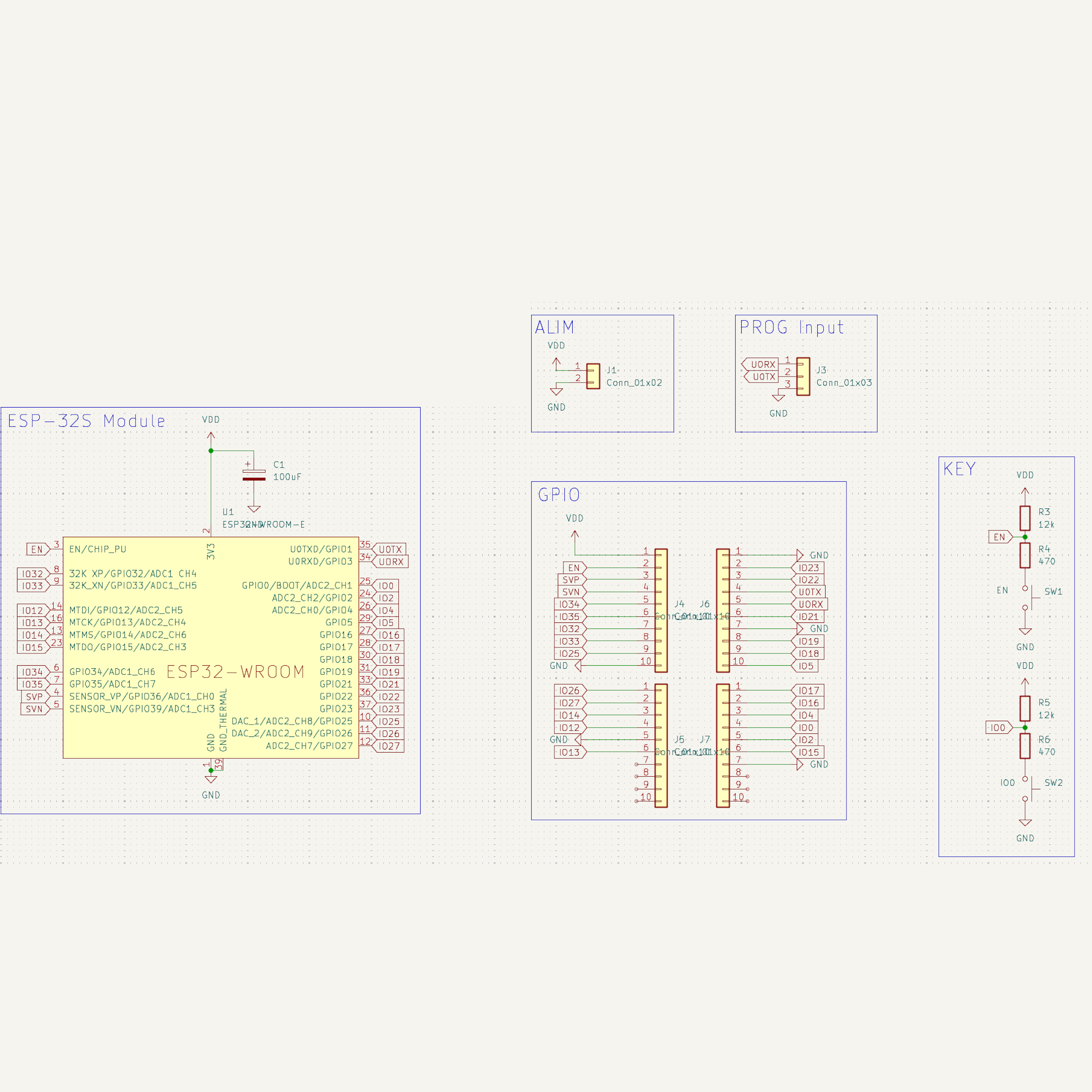
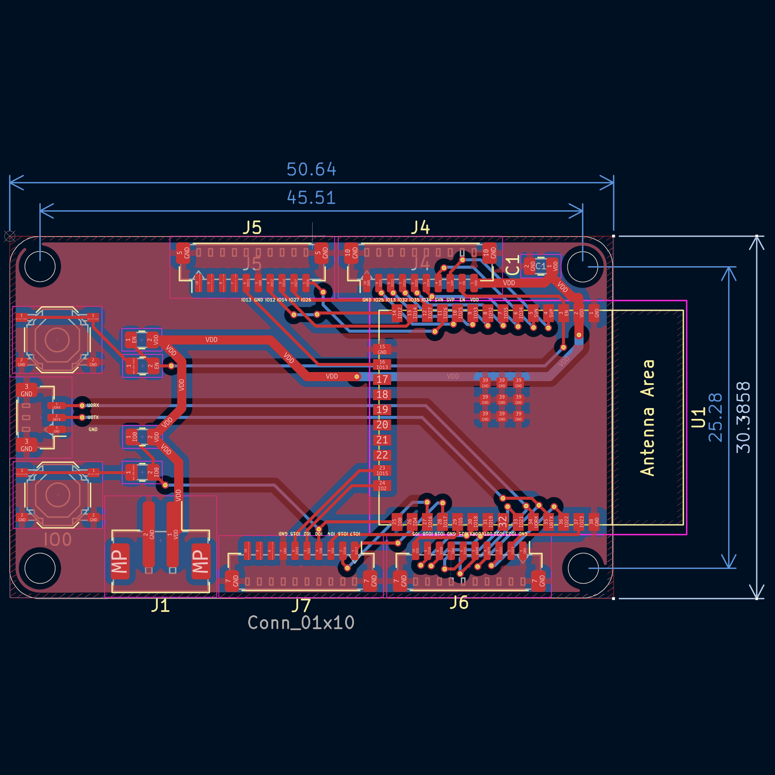
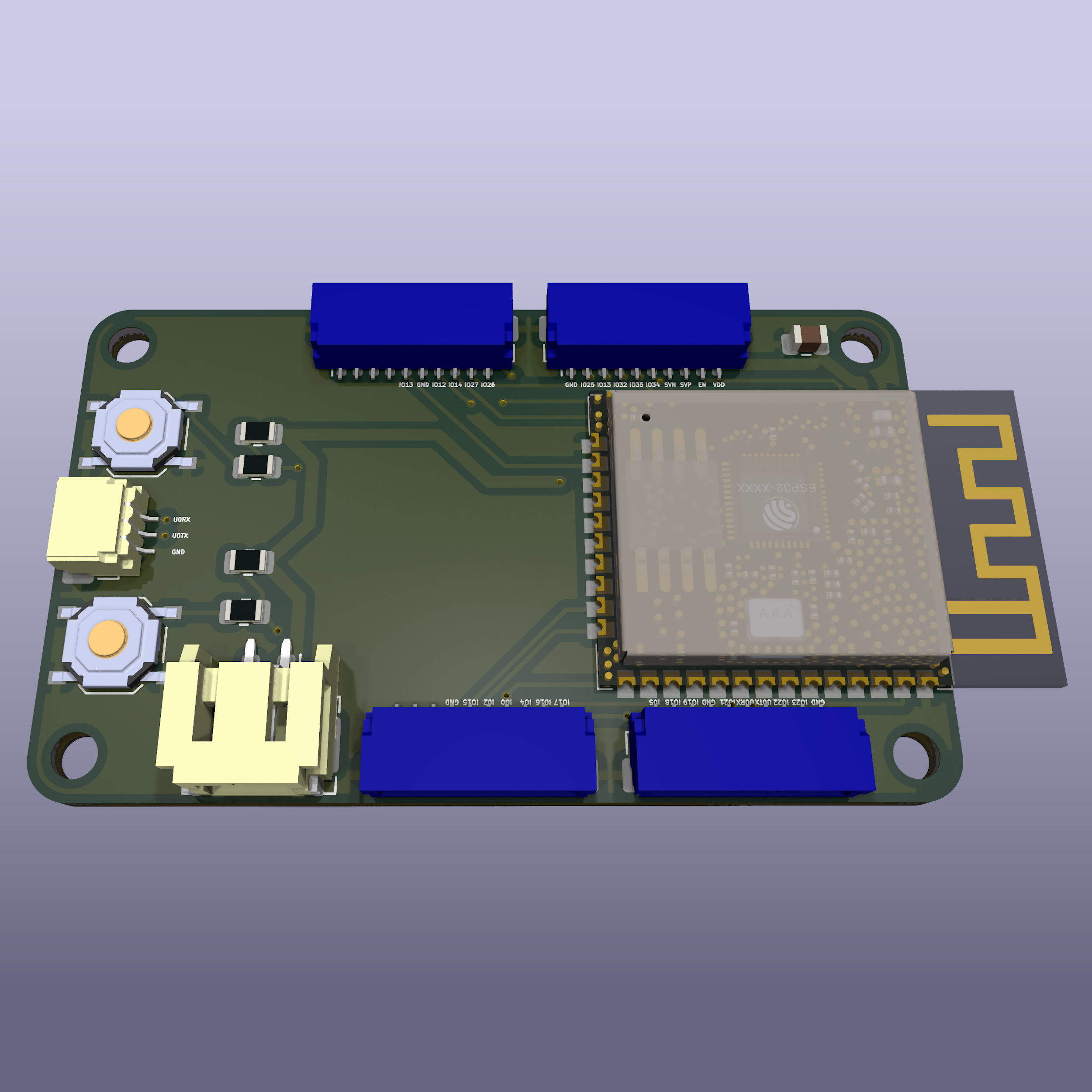
Esp32InterfacePCB is an open-source PCB designed to provide a reliable interface between an Espressif ESP32-WROOM-32E module and various external modules using JST-SM & JST-SH connectors. This PCB simplifies ESP32 integration into embedded, IoT, and home automation projects.
🎯 Purpose
- 🔌 Modular Interface: Facilitates the connection between an ESP32-WROOM-32E and other peripherals.
- 📏 Compact & Optimized Design: Suitable for embedded project constraints.
- 🛠️ Open-source & Customizable: Modify and adapt the design to fit your specific needs.
📝 Features
| 🏷️ Feature | 🔍 Description |
|---|---|
| 🔌 ESP32 Interface | Compatible with the ESP32-WROOM-32E module |
| 📡 Connectors | JST-SM & JST-SH for easy connections |
| ⚡ Power Supply | Supports 3.3V |
| 🛠️ GPIO Access | Access to key GPIO pins for seamless integration |
| 🔧 Capacitors | Decoupling capacitors for signal stability |
| 🖥️ PCB Design | Open-source & customizable |
| 🌍 Use Cases | IoT, embedded systems, automation, robotics, rapid prototyping |
📐 PCB Design Preview
| 📜 Schematic | 🖥️ PCB Layout | 🏗️ 3D |
|---|---|---|
 |
 |
 |
HV2LV-PowerJST
🔋 Regulator 4.8V-15V -> 3.3V
HV2LV-PowerJST is an open-source PCB designed to step down 4.8V - 15V to a stable 3.3V output using an AMS1117 voltage regulator. The board features JST-PH connectors for easy integration into embedded projects, IoT devices, and prototyping setups.
🎯 Purpose
- 🔌 Efficient power conversion: Converts input voltages from 4.8V to 15V down to a fixed 3.3V.
- 📏 Compact and Adafruit-compatible: Designed to fit within Adafruit’s standard PCB footprint.
- 🛠️ Open-source and customizable: Modify and adapt the design to suit your specific needs.
📝 Features
| 🏷️ Feature | 🔍 Description |
|---|---|
| ⚡ Input Voltage | 4.8V - 15V |
| 🔋 Output Voltage | 3.3V (fixed) |
| 🛠️ Regulator | AMS1117-3.3 |
| 🔌 Connector 1 | JST-PH (Input Voltage) |
| 🔌 Connector 2 | JST-PH (3.3V Output) |
| 🔧 Capacitors | 4 decoupling capacitors for stability |
| 🖥️ PCB Design | Open-source & customizable |
| 🌍 Use Cases | Powering 3.3V embedded systems, IoT devices, and sensors |
📐 PCB Design Preview
| 📜 Schematic | 🖥️ PCB Layout | 🏗️ 3D |
|---|---|---|
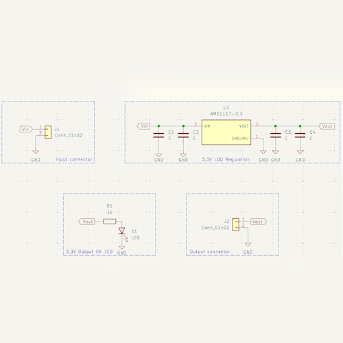 |
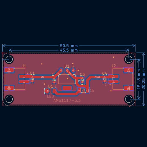 |
 |
HeaterControl-Shield
🔥 STM32 Shield for Heat Control
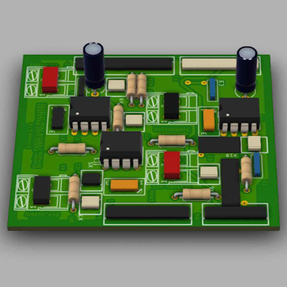
HeaterControl-Shield is an open-source electronic board designed to control a heating resistor, measure the consumed current, and detect the temperature near the heating resistor. This board is shaped as an Arduino shield and optimized for use with an STM32 Nucleo.
🎯 Main Features
- 🔥 Heating resistor control via an N-channel MOSFET.
- ⚡ Current consumption measurement using a shunt resistor and an operational amplifier.
- 🌡️ Temperature sensing using a thermistor integrated into a Wheatstone bridge, amplified by an instrumentation amplifier.
- 🛠️ Open-source and customizable design to adapt to specific project needs.
📝 Technical Specifications
| 🏷️ Feature | 🔍 Description |
|---|---|
| 🔌 Power Input | 5V - 12V |
| 🔥 Heating Control | N-channel MOSFET for power control |
| ⚡ Current Measurement | Shunt resistor + Operational amplifier |
| 🌡️ Temperature Sensing | Wheatstone bridge + Instrumentation amplifier |
| 🔄 Interface | Compatible with Arduino Shield and STM32 Nucleo |
| 🖥️ PCB Design | Open-source & customizable |
| 🌍 Applications | Thermal control projects, embedded systems, temperature regulation |
📐 PCB Preview
| 📜 Schematic | 🖥️ PCB Layout | 🏗️ 3D View |
|---|---|---|
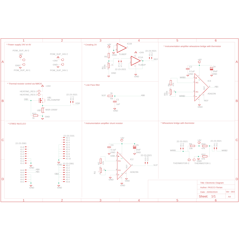 |
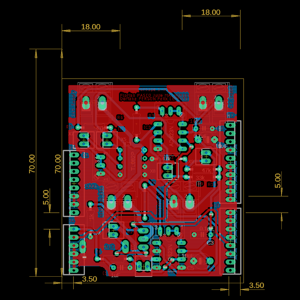 |
 |
🔗 Main Connections
| Pin | Function |
|---|---|
| VIN | Main power input |
| GND | Ground |
| HEAT_CTRL | PWM signal to activate heating |
| CURR_SENSE | Amplified output of current measurement |
| TEMP_SENSE | Amplified output of temperature measurement |
Max98357I2SAmp
🎵 Compact I2S Amp with JST Connectors
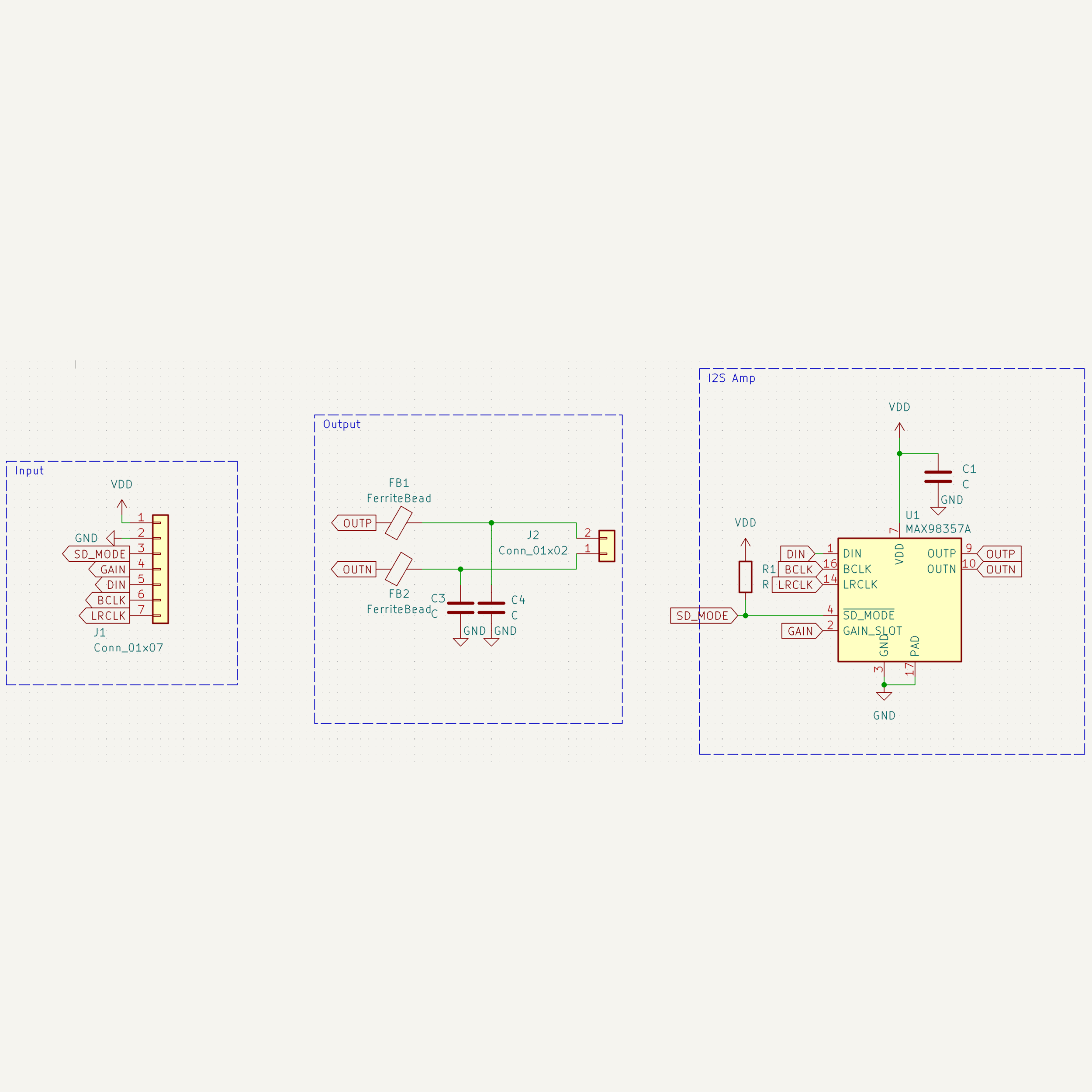
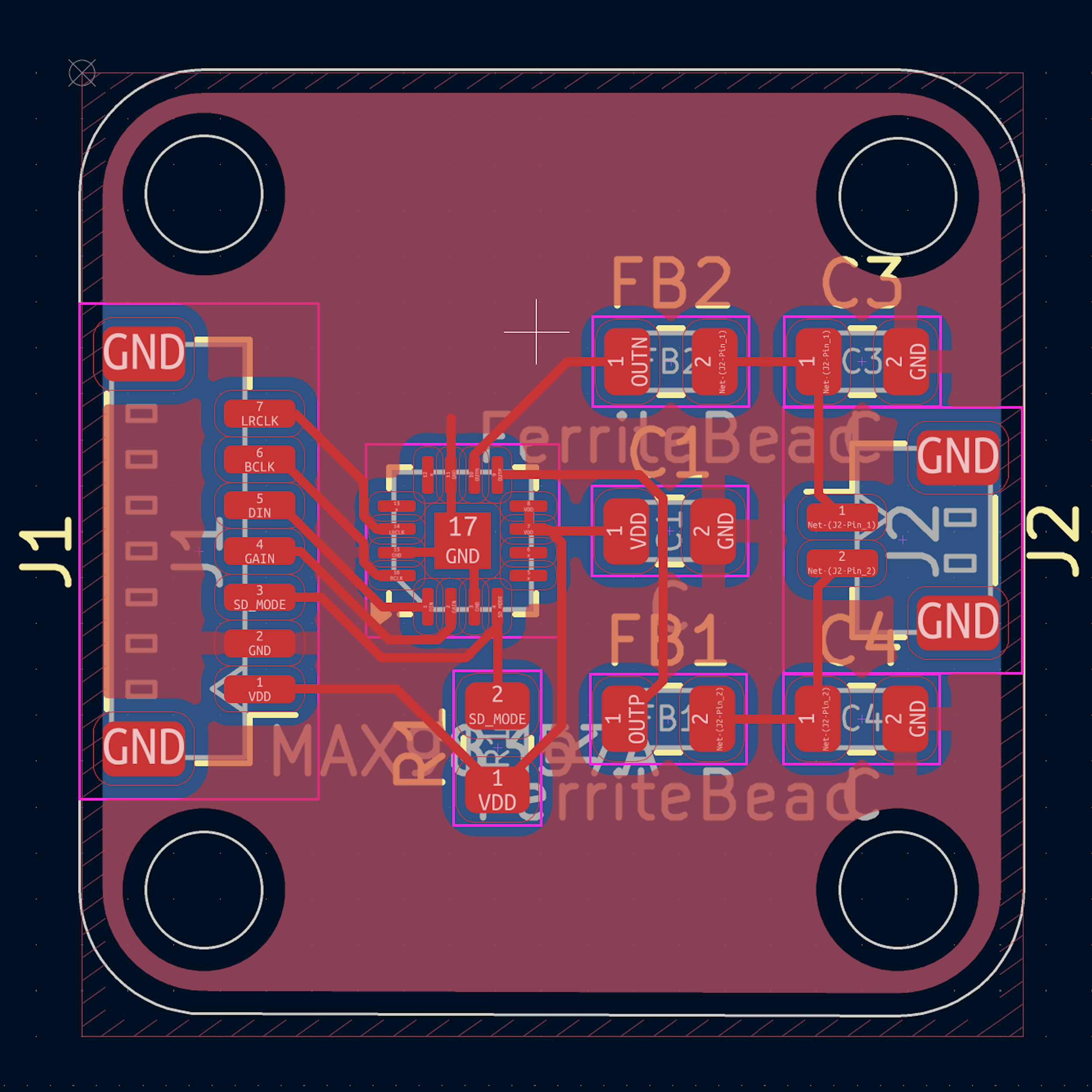
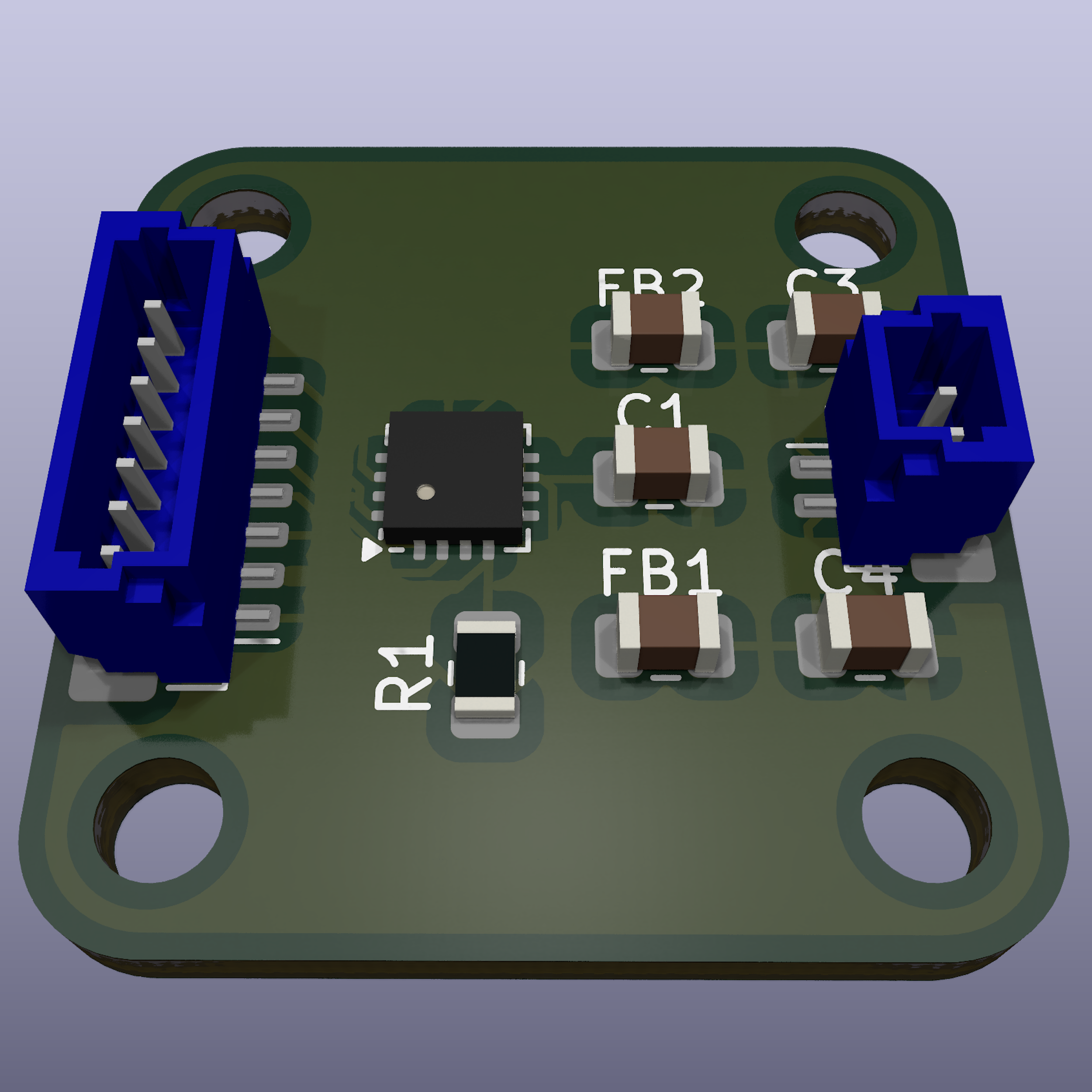
This is an open-source KiCad redesign of the Adafruit MAX98357 I2S Amp Breakout, featuring modified input and output connectors using JST-SH & JST-PH. This version maintains the compact, efficient, and high-performance Class-D amplifier while enhancing connectivity for ease of integration into various projects.
🎯 Purpose
- 🔌 Enhanced Connectivity: Uses JST-SH & JST-PH connectors for secure and reliable connections.
- 🎵 Digital Audio Amplification: Converts I2S digital audio to amplified analog output.
- 📏 Compact & Efficient: Optimized for embedded, IoT, and portable applications.
- 🛠️ Open-source & Customizable: Modify the design to fit your needs.
📝 Features
| 🏷️ Feature | 🔍 Description |
|---|---|
| 🎵 I2S Input | Accepts standard I2S digital audio format |
| 🔊 Amplification | Class-D amplifier delivering up to 3.2W into 4Ω |
| 🔌 Connectors | JST-SH for I2S input, JST-PH for speaker output |
| ⚡ Power Supply | Operates from 2.7V to 5.5V |
| 🔥 Efficiency | Class-D architecture with built-in thermal & overcurrent protection |
| 📜 PCB Design | Fully designed in KiCad, optimized for easy manufacturing |
📐 PCB Design Preview
| 📜 Schematic | 🖥️ PCB Layout | 🏗️ 3D |
|---|---|---|
 |
 |
 |
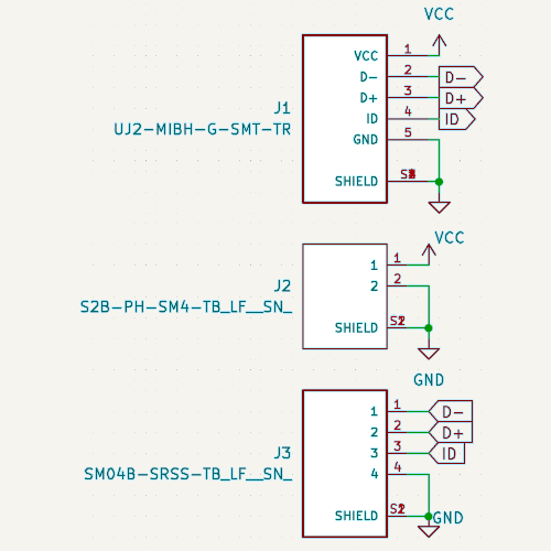
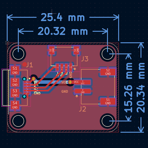
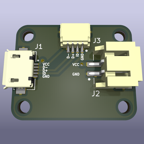
MicroUSB2JST
🔌 MicroUSB -> JST-SH & JST-PH
MicroUSB2JST is an open-source PCB that acts as a bridge between a Micro USB port and JST connectors (JST-SH and JST-PH). This module is designed to simplify connections for embedded projects, prototyping, and power distribution.
🎯 Purpose
- 🔌 Convenient power and data interface: Easily connect USB power or data lines to JST-equipped devices.
- 📏 Compact and Adafruit-compatible: Designed to fit within Adafruit’s standard PCB footprint.
- 🛠️ Open-source and customizable: Modify and adapt the design to suit your specific needs.
📝 Features
| 🏷️ Feature | 🔍 Description |
|---|---|
| 🔌 Connector 1 | Micro USB (⚡ power & 🔄 data) |
| 🔌 Connector 2 | JST-PH (⚡ higher current capacity) |
| 🔌 Connector 3 | JST-SH (📏 small form factor) |
| 🖥️ PCB Design | 🆓 Open-source & ✏️ customizable |
| 🎯 Use Cases | ⚡ Power distribution, 🛰️ sensor connections, 🤖 embedded systems |
📐 PCB Design Preview
| 📜 Schematic | 🖥️ PCB Layout | 🏗️ 3D |
|---|---|---|
 |
 |
 |
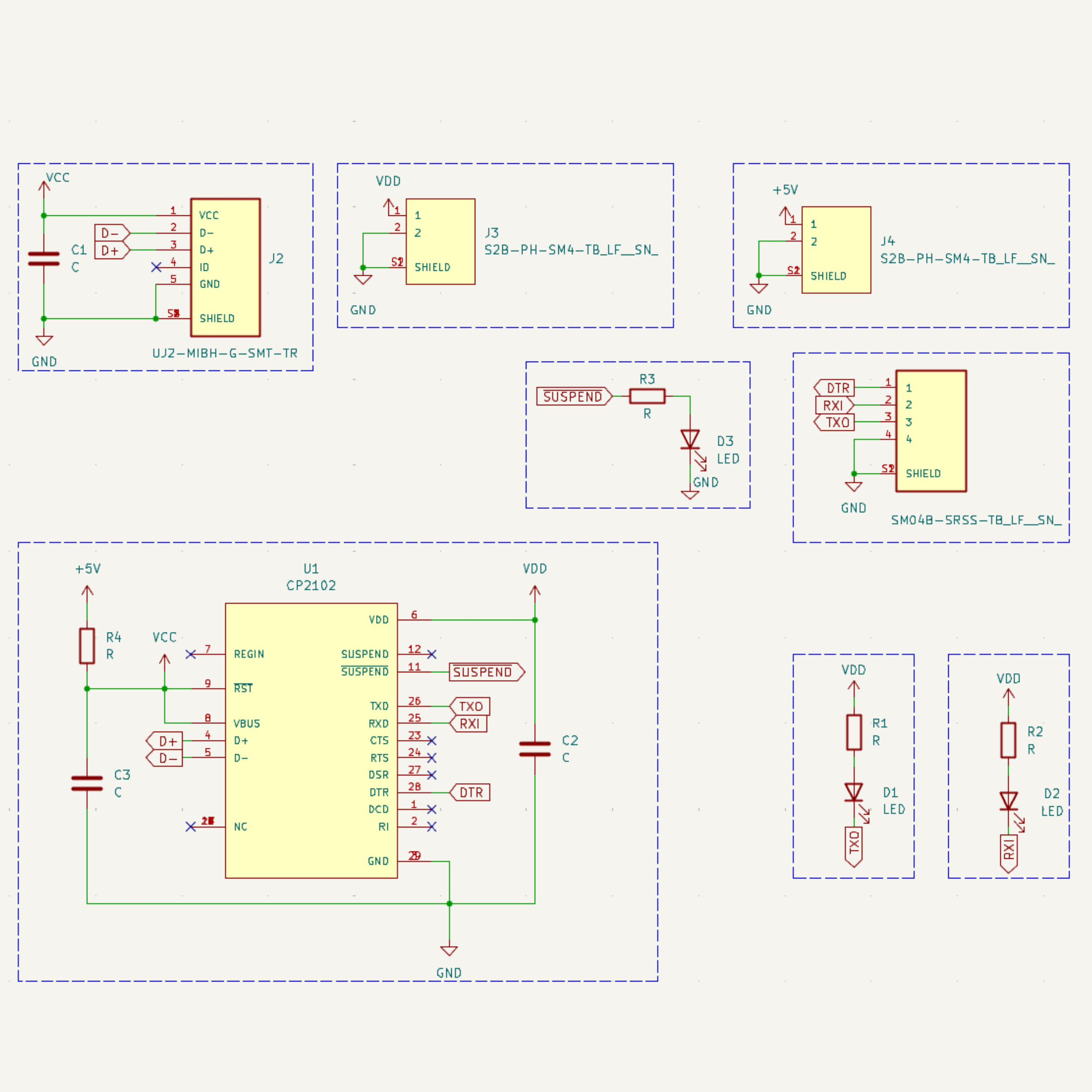
UsbUartBridge
🔌 USB-to-UART bridge for embedded systems
UsbUartBridge is an open-source PCB designed to provide a USB-to-UART bridge for seamless serial communication between a computer and microcontrollers. The board features JST-SH & JST-PH connectors for easy integration into embedded projects, IoT devices, and prototyping setups.
🎯 Purpose
- 🔌 Reliable USB-to-Serial Conversion: Enables communication between a PC and embedded systems via UART.
- 📏 Compact and Adafruit-compatible: Designed to fit within Adafruit’s standard PCB footprint.
- 🛠️ Open-source and customizable: Modify and adapt the design to suit your specific needs.
📝 Features
| 🏷️ Feature | 🔍 Description |
|---|---|
| 🔌 USB Interface | Micro-USB (for PC connection) |
| 📡 UART Interface | TX, RX, DTR |
| 🔋 Voltage Options | 3.3V & 5V selectable output |
| 🛠️ Connectivity | JST-SH & JST-PH connectors for easy integration |
| 🔧 Capacitors | Decoupling capacitors for stability |
| 🖥️ PCB Design | Open-source & customizable |
| 🌍 Use Cases | Debugging & Programming microcontrollers, IoT device communication, serial data transfer |
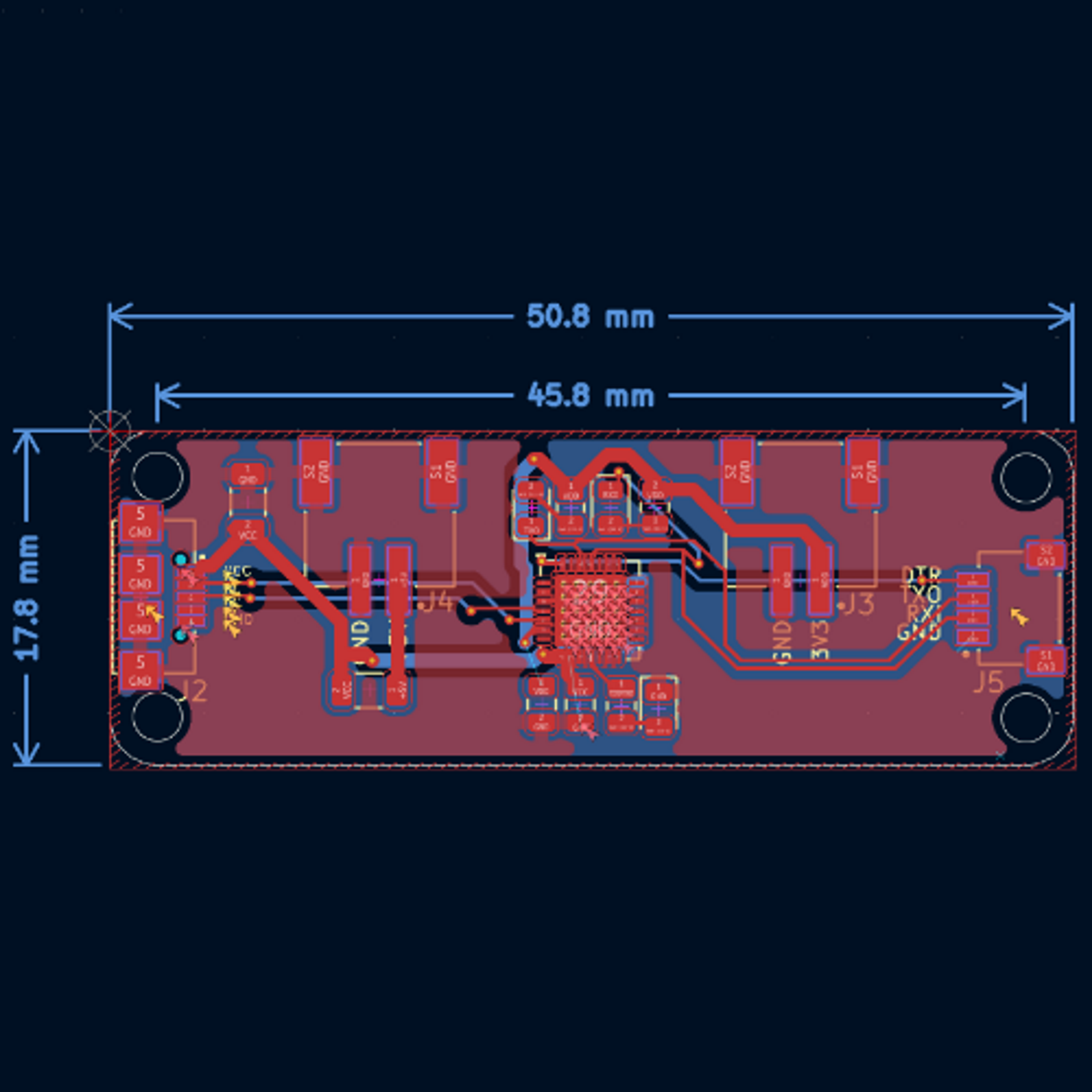
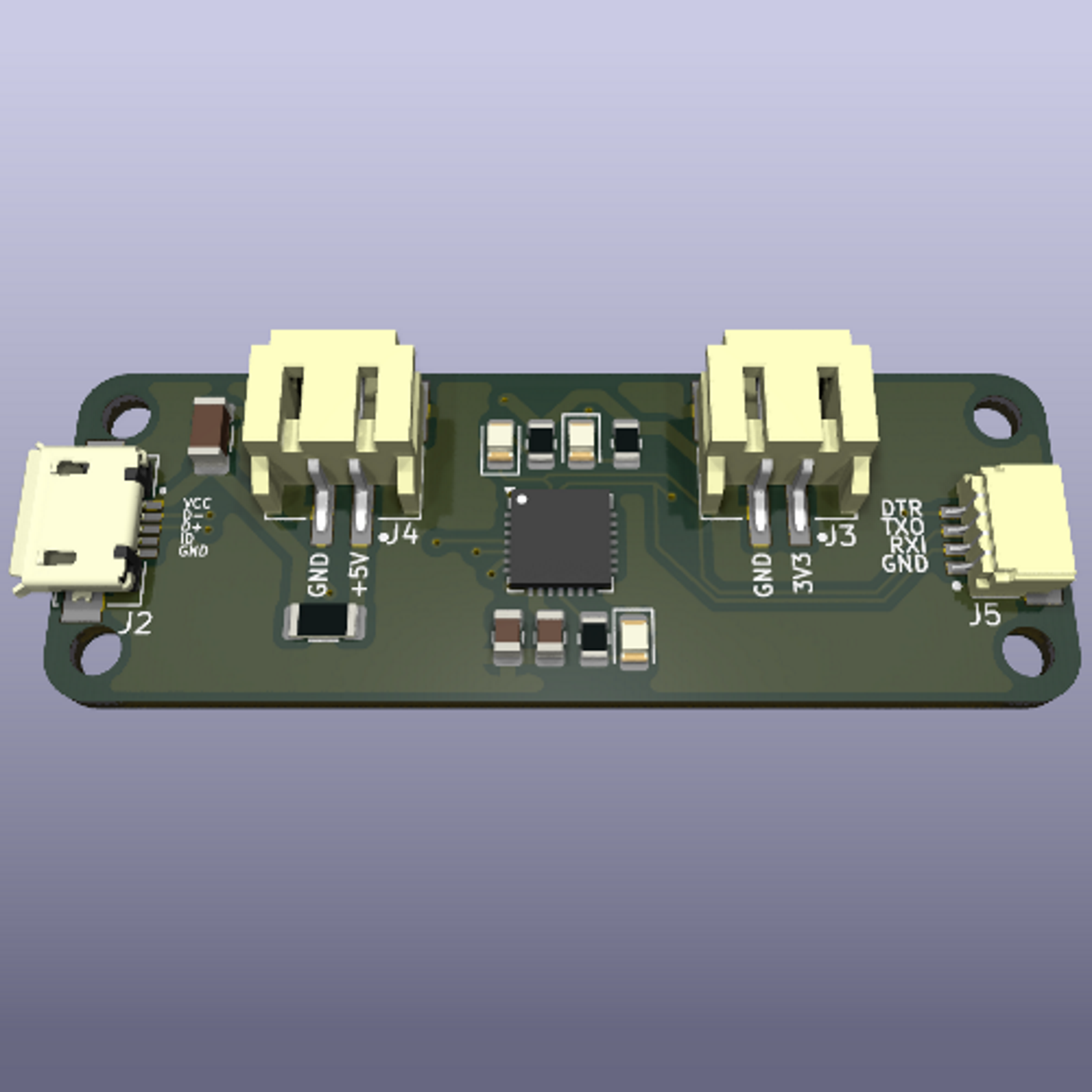
📐 PCB Design Preview
| 📜 Schematic | 🖥️ PCB Layout | 🏗️ 3D |
|---|---|---|
 |
 |
 |
BCHDecoderVHDL
🧮 BCH decoder FPGA design
BCHDecoderVHDL is an open-source project aimed at designing a BCH error-correcting decoder in VHDL, built for FPGA implementation using an Avalon interface. This hardware module is integrated into a SoC system based on an Intel Cyclone V and deployed on a DE0-CV development board running at 25 MHz.
🎯 Purpose
- 🧮 Error Correction: Implements BCH decoding for binary data error detection and correction.
- 🔗 Avalon Interface Compatibility: Designed to connect seamlessly to Avalon-compliant systems.
- 🧩 Quartus Integration: Ready for integration into Intel Quartus projects targeting DE0-CV boards.
- 🧠 CPU Exploitation: Enables communication with a Nios II or other Avalon master for data exchange.
📝 Features
| 🏷️ Feature | 🔍 Description |
|---|---|
| 🧮 BCH Decoder | Implements syndrome calculation, Berlekamp-Massey algorithm, Chien Search |
| 🔗 Avalon Interface | Supports Avalon-MM or Avalon-ST as needed |
| ⚙️ VHDL Design | Modular, synthesizable VHDL code |
| 🧠 CPU-Controlled | Controlled by an Avalon master processor |
| 🧪 VHDL Testbench | Comes with a simulation testbench for functional validation |
| 🧱 DE0-CV Ready | Optimized for 25 MHz operation on DE0-CV |
| 🖥️ Quartus Project | Integrated via Qsys / Platform Designer |
| 📦 Open-source | Fully modifiable and extensible HDL source code |
📐 Design Architecture Preview
| ⚙️ Internal Architecture | 🖥️ Qsys Integration |
|---|---|
 |
 |
🗂️ Project Structure
BCHDecoderVHDL/
├── ip/
│   └── BCH/
│       ├── bch.vhd         # VHDL source files
│       └── simulation/     # VHDL testbenches
├── DE0_CV.qpf              # Quartus project file
├── software/               # Scripts or files related to software development
📦 Use Cases
- ✅ Embedded communication systems
- ✅ FPGA-based secure data transmission
- ✅ Educational demonstration of error-correcting codes
StateMachineSafe
🔐 Safe control via state machine!
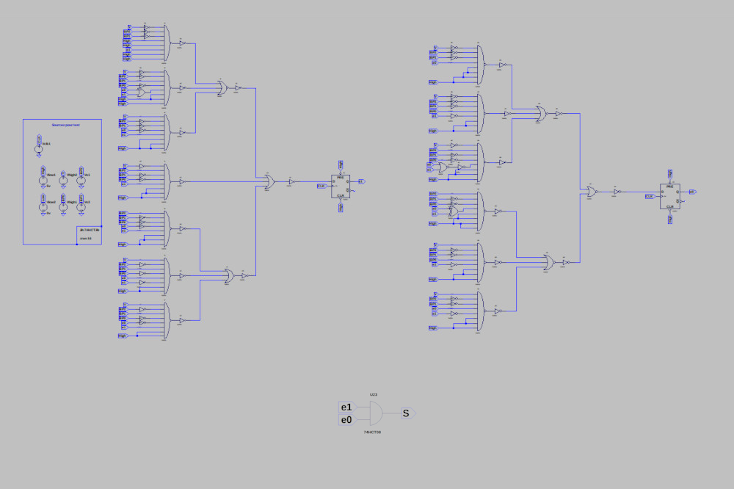
StateMachineSafe is a project aimed at designing and simulating a state machine to manage the opening and closing of a safe. This machine is built using D flip-flops and logic gates, ensuring precise logical control of the mechanism.
🎯 Purpose
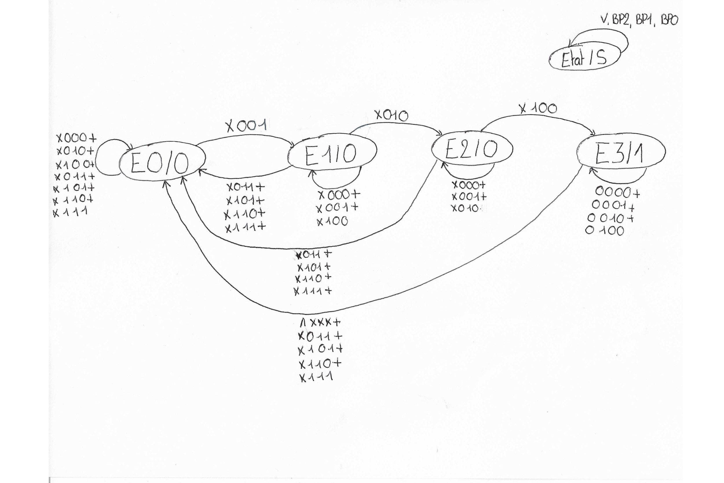
- 📜 State Machine Design: Development of a state graph defining the safe’s behavior.
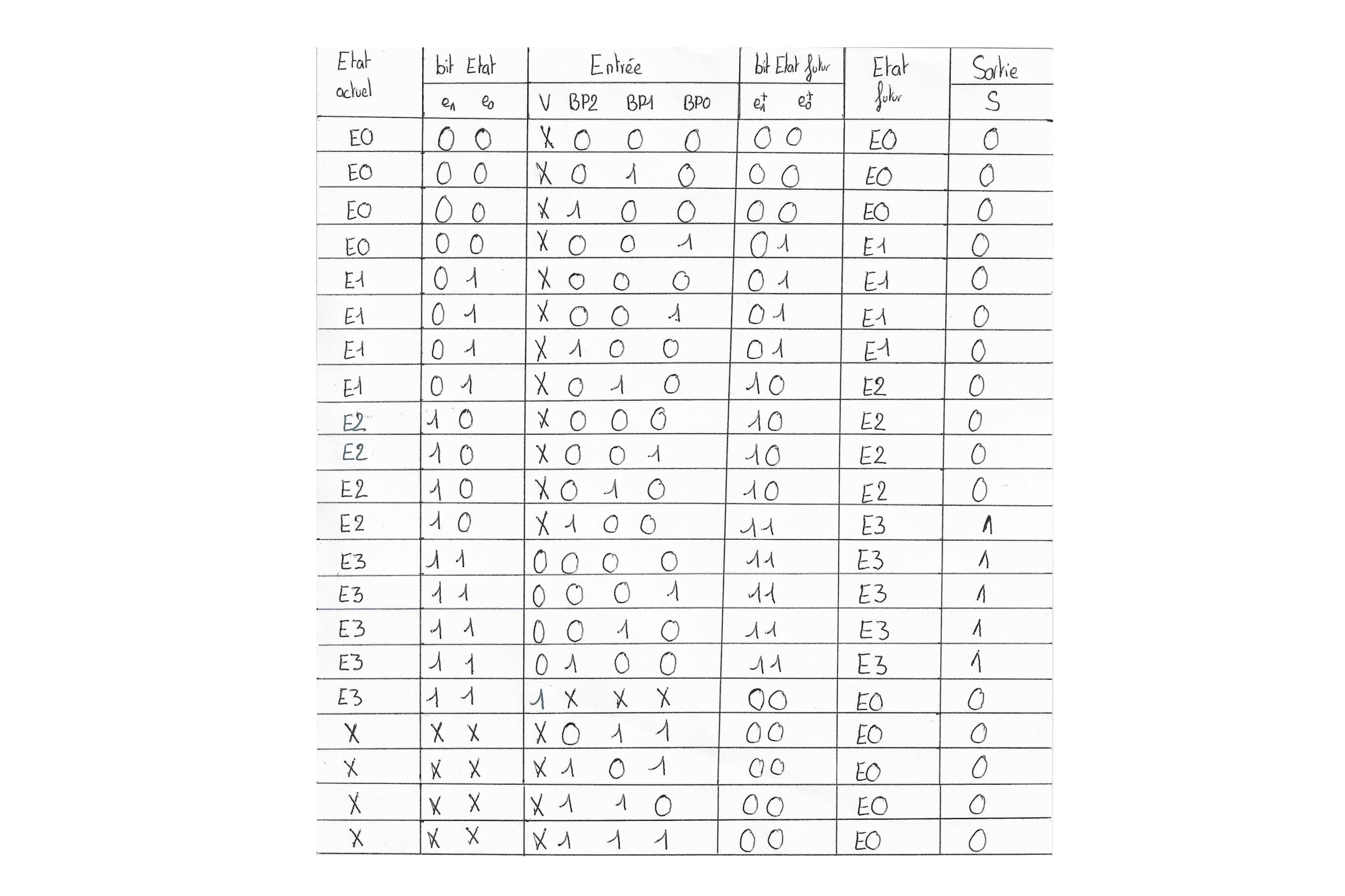
- 🧮 Transition Table and Karnaugh Map: Derivation of logical equations necessary for system operation.
- 🔬 LTSpice Simulation: Verification and validation of the logical circuit through LTSpice simulation.
- 🔑 Secure Access Management: Implementation of a reliable mechanism ensuring the safe’s opening and closing according to a defined sequence.
📝 Features
| 🏷️ Feature | 🔍 Description |
|---|---|
| 🔄 State Machine | Modeling of the control system with a state graph |
| 📊 Transition Table | Definition of transitions between states |
| 📏 Karnaugh Map | Simplification of logical equations |
| 🛠️ Hardware Implementation | Use of D flip-flops and logic gates |
| 🖥️ LTSpice Simulation | Verification of behavior through simulation |
📐 System Architecture
| 🎭 State Graph | 🗂️ Transition Table | ⚡ Logic Circuit |
|---|---|---|
 |
 |
 |
AMS1117DC3V3
⚡ AMS1117 3.3V Buck reverse-engineered
An open-source reverse-engineered version of the AMS1117 3.3V DC-DC buck converter module, based on the original component available here.
This project aims to provide insights into DC-DC voltage regulation and offer a customizable alternative for power management in embedded systems.
🎯 Purpose
- 🔍 Reverse engineering: Understanding the design and functionality of the AMS1117-based voltage regulator.
- 🛠️ Skill development: Enhancing expertise in PCB design and power electronics.
- 🔄 Future adaptation: Leveraging this knowledge to develop custom voltage regulation solutions for embedded applications.
📝 Features Comparison: Original vs. Reverse-Engineered
| Feature | Original Module | Reverse-Engineered Version |
|---|---|---|
| 🖥️ PCB Design | Proprietary | Open-source & customizable |
| 🔌 Input Voltage | 4.8V - 15V | 4.8V - 15V |
| ⚡ Output Voltage | 3.3V (fixed) | 3.3V (fixed) |
| 📦 Max Current | 1500 mA | 1500 mA |
| 🏷️ Regulator Chip | AMS1117-3.3 | AMS1117-3.3 |
| 👐 Mechanical Drawing | 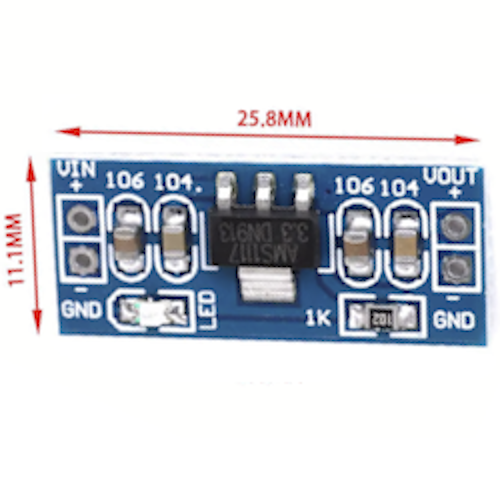 |
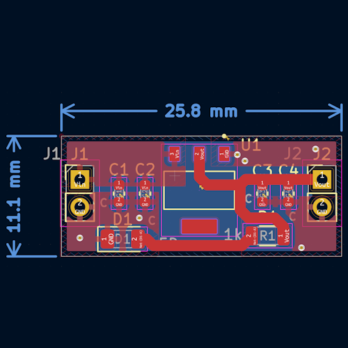 |
| 📝 Reverse-Engineered Schematic | N/A | 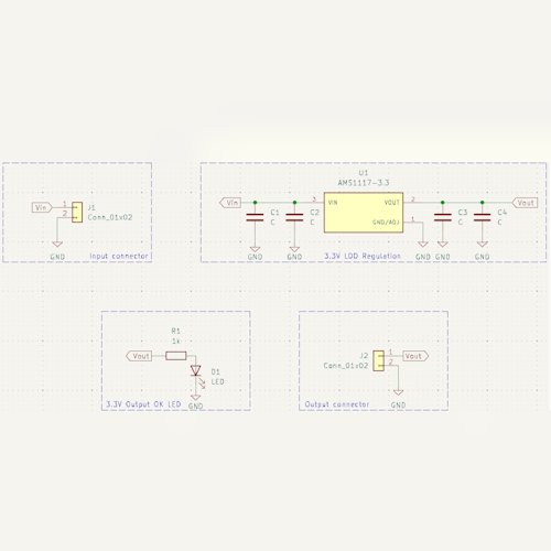 |
| 📷 Photo | 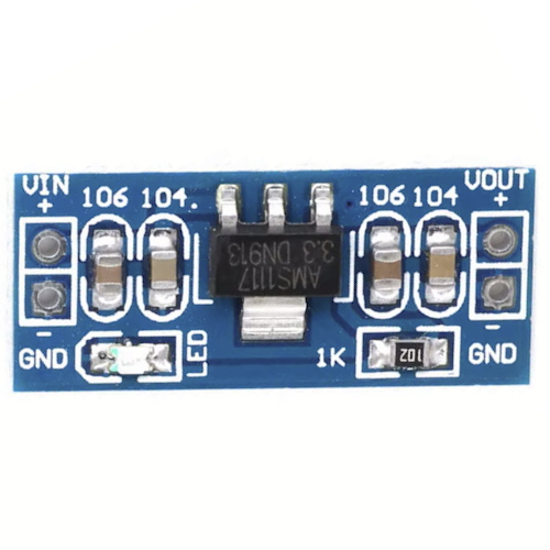 |
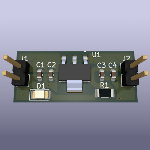 |
🛠️ How to Use
📌 Wiring Guide
| Pin | Description |
|---|---|
| VIN | Input Voltage (4.8V - 15V) |
| GND | Ground |
| VOUT | Regulated 3.3V Output |
CP2102USB2UART
🔌 CP2102 USB to UART reverse-engineered
An open-source reverse-engineered version of the CJMCU CP2102 USB to UART TTL adapter, based on the original component available here. This project aims to provide insights into USB-to-serial communication and offer a customizable alternative for embedded system developers.
🎯 Purpose
- 🔍 Reverse engineering: Understanding the design and functionality of the CP2102USB2UART.
- 🛠️ Skill development: Enhancing expertise in PCB design and USB-to-serial communication.
- 🔄 Future adaptation: Leveraging this knowledge to develop custom USB-to-UART solutions for embedded systems.
📝 Features Comparison: Original vs. Reverse-Engineered
| Feature | Original Module | Reverse-Engineered Version |
|---|---|---|
| 🖥️ PCB Design | Proprietary | Open-source & customizable |
| 🔌 USB Connector | Micro USB | Micro USB |
| 🏷️ Chipset | CP2102 | CP2102 |
| 📌 Pin Mapping | 6-Pin UART TTL | 6-Pin UART TTL |
| ⚡ Supported Voltage | 3.3V / 5V | 3.3V / 5V |
| 👐 Mechanical Drawing | 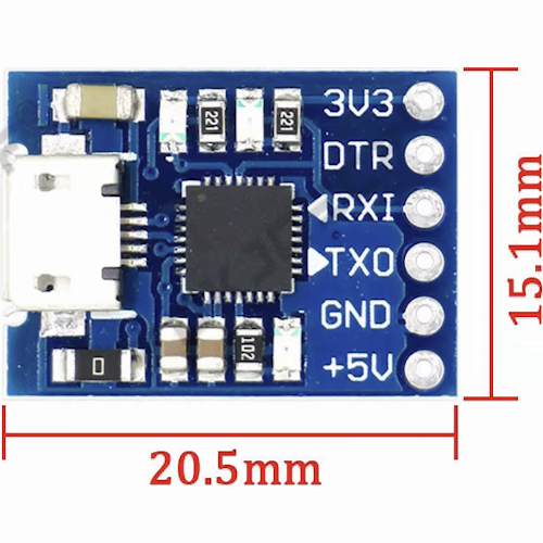 |
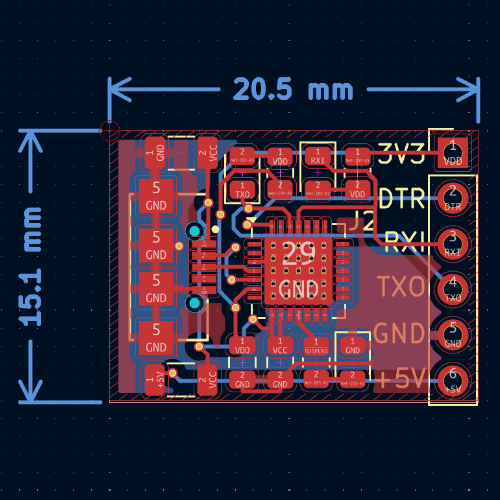 |
| 📝 Reverse-Engineered Schematic | N/A | 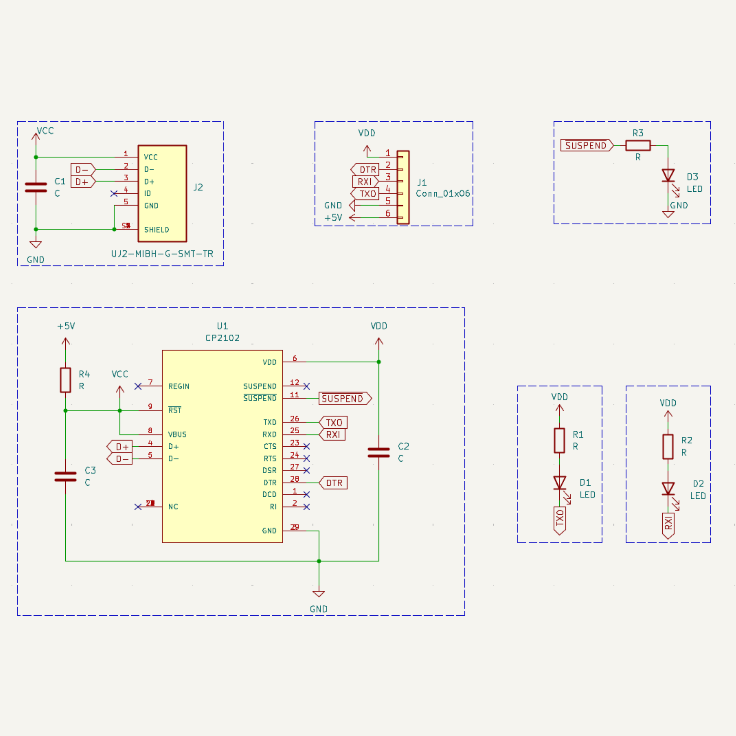 |
| 📷 Photo | 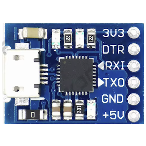 |
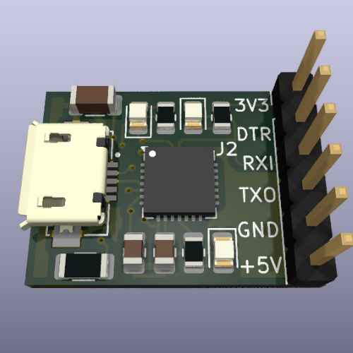 |
🛠️ How to Use
📌 Wiring Guide
| CP2102 Pin | Description |
|---|---|
| TXD | Transmit Data |
| RXD | Receive Data |
| GND | Ground |
| 3V3 | 3.3V Power Output |
| 5V | 5V Power Output |
| DTR | Data Terminal Ready |
MicroUSB2DIP
🔌 Micro USB to DIP reverse-engineered
This is an open-source reverse-engineered version of a Micro USB to DIP adapter, based on the original component available here. The goal of this project was to practice reverse engineering as a learning exercise and to prepare for a future adaptation in a larger project.
🎯 Purpose
- 🔍 Reverse engineering: Understanding the design and functionality of this micro USB to DIP connector.
- 🛠️ Skill development: Enhancing expertise in PCB design and hardware analysis skills.
- 🔄 Future adaptation: Leveraging this knowledge for embedded applications.
📝 Features Comparison: Original vs. Reverse-Engineered
| Feature | Original Module | Reverse-Engineered Version |
|---|---|---|
| 🖥️ PCB Design | Proprietary | Open-source & customizable |
| 🔌 Connector Type | Micro USB | Micro USB |
| 📌 Pin Mapping | Standard DIP | Standard DIP |
| 👐 Mechanical Drawing | 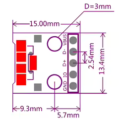 |
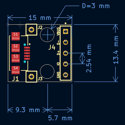 |
| 📝 Reverse-Engineered Schematic | N/A | 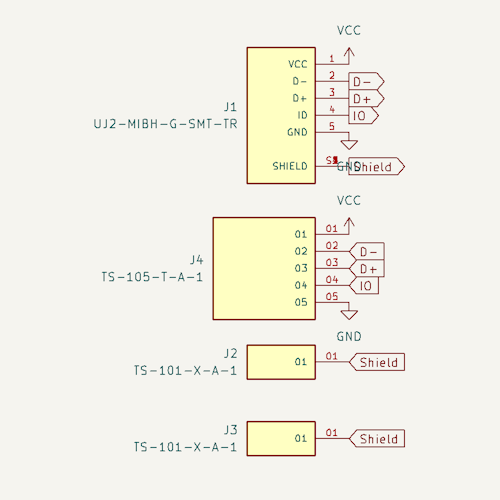 |
| 📷 Photo | 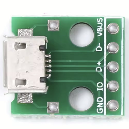 |
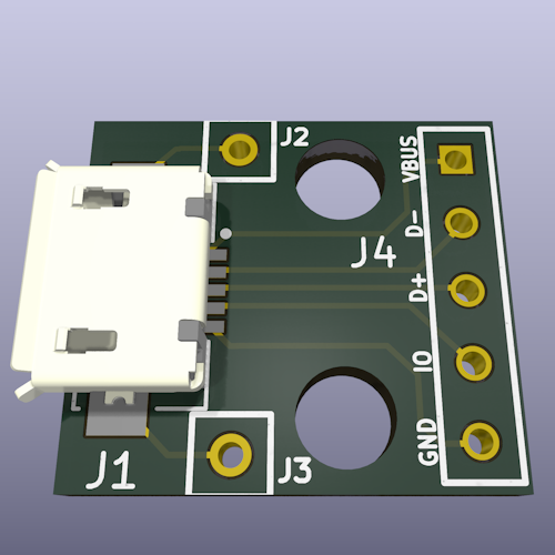 |
🛠️ How to Use
📌 Wiring Guide
| Pin | Function |
|---|---|
| VBUS | +5V |
| D- | Data - |
| D+ | Data + |
| ID | Mode detect (A: GND, B: Open) |
| GND | Ground |
AntiVuvuzelaFilter
🎵 Noise filter for clear audio 🎙️
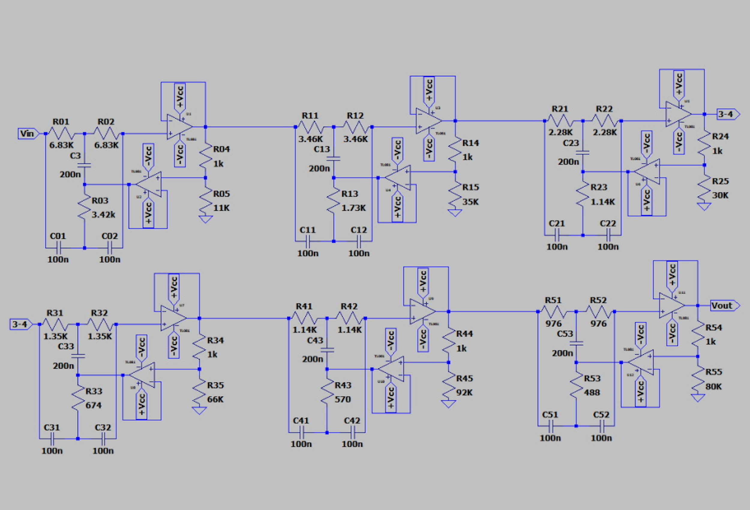
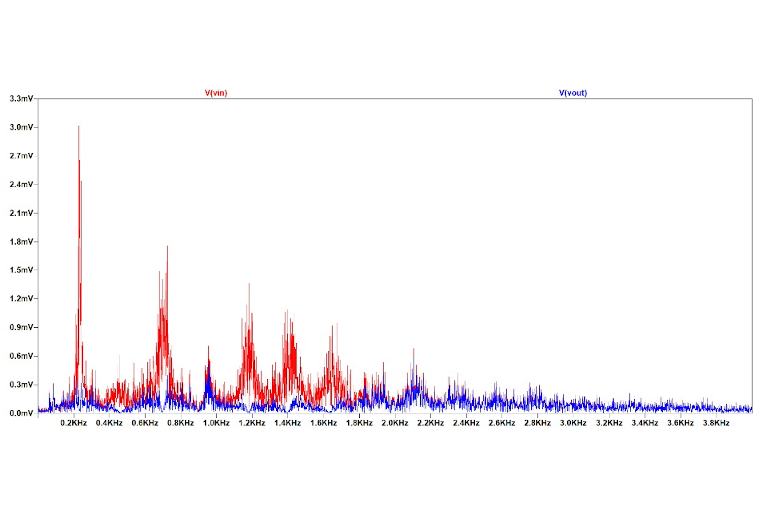
Anti-Vuvuzela Filter is an open-source project dedicated to second-order analog filters and beyond. This project was initially developed to design an “anti-vuvuzela” filter, aiming to attenuate the distinctive and persistent sound of vuvuzelas while preserving the clarity of commentators’ voices during the 2010 FIFA World Cup.
🎯 Purpose
- 🔇 Targeted Noise Reduction: Specifically designed to attenuate vuvuzela noise while maintaining the intelligibility of speech.
- 🎚 Second-Order Analog Filtering: Utilizing advanced filtering techniques for efficient noise cancellation.
- 🛠️ Open-source and Customizable: Modify and adapt the design for other audio filtering applications.
📝 Features
| 🏷️ Feature | 🔍 Description |
|---|---|
| 🎼 Filter Type | Second-order analog filter |
| 🎯 Target Frequency | 233 Hz (typical vuvuzela frequency) |
| 🎙 Voice Preservation | Maintains speech clarity |
| 🔧 Components | Resistors, capacitors, and operational amplifiers |
| 🖥️ Simulation Tools | Jupyter Notebook, LTSpice |
| 🛠 Real-world Testing | Assembled and tested in real conditions |
| 🔌 Input | Analog audio signal |
| 🔊 Output | Cleaned audio signal with reduced vuvuzela noise |
| 🌍 Use Cases | Audio signal processing, speech enhancement, noise reduction |
📐 Simulation & Testing
| 🛠️ LTSpice Circuit | 📜 Simulation |
|---|---|
 |
 |
DirectSequenceSpreadSpectrum
📡 Direct Sequence Spread Spectrum Study
This project investigates spread spectrum transmission using a direct sequence spreading technique. Performance evaluation is first conducted over a Gaussian channel, with the possible presence of a jammer. Then, an experimental transmission over an acoustic channel is performed. The entire study is carried out in the Jupyter Notebook environment.
🎯 Purpose
- 🌌 Spread Spectrum Transmission: Analyze direct sequence spread spectrum (DSSS) techniques.
- 📊 Performance Evaluation: Assess system performance under Gaussian noise and jamming conditions.
- 🔊 Acoustic Channel Experimentation: Implement DSSS transmission over an acoustic medium.
- 🖥️ Jupyter Notebook Implementation: Develop and document the study in a Jupyter Notebook environment.
📝 Features
| 🏷️ Feature | 🔍 Description |
|---|---|
| 🌌 Direct Sequence DSSS | Implements direct sequence spread spectrum transmission |
| 📊 Performance Metrics | Evaluate system performance in different noise conditions |
| 🚀 Jamming Resilience | Study system robustness against intentional interference |
| 🔊 Acoustic Transmission | Test DSSS communication over an acoustic channel |
| 🖥️ Jupyter Notebook | Full implementation and documentation in Python |
🔬 Methodology
| 🌌 Signal Spreading | 📊 Performance Evaluation | 🔊 Acoustic Transmission |
|---|---|---|
 |
 |
 |
📚 Architecture
/spread-spectrum-transmission
│── notebooks/
│ ├── 01_transmitter.ipynb # DSSS transmitter implementation
│ ├── 02_receiver.ipynb # DSSS receiver implementation
│ ├── 03_awgn_channel.ipynb # AWGN channel simulation
│ ├── 04_performance.ipynb # Performance evaluation (BER, SNR)
│ ├── 05_jamming.ipynb # Jamming impact analysis
│ ├── 06_dbpsk.ipynb # DBPSK implementation
│ ├── 07_audio_transmission.ipynb # Audio experimentation
│── src/
│ ├── dsp_utils.py # Signal processing utilities
│ ├── modulation.py # Implementation of BPSK and DBPSK modulations
│ ├── spreading.py # Spread sequence generation
│ ├── filtering.py # RRC filters and delay compensation
│── data/
│ ├── audio/ # Audio signals recorded for testing
│ ├── parameters/ # Transmission parameters saved
│ ├── images/ # Images used for transmission
│── results/
│ ├── figures/ # Graphics generated (spectrograms, BER, etc.)
│ ├── logs/ # Experiment results
│── README.md # Project documentation
│── requirements.txt # Libraries required (numpy, scipy, matplotlib...)
│── environment.yml # Jupyter configuration file
📚 Report & Code
The project deliverables include:
- A detailed report illustrating the results obtained for each step.
- The full implementation in a Jupyter Notebook.
DtmfCodeAnalyzer
🎶 Analyze and filter DTMF signals
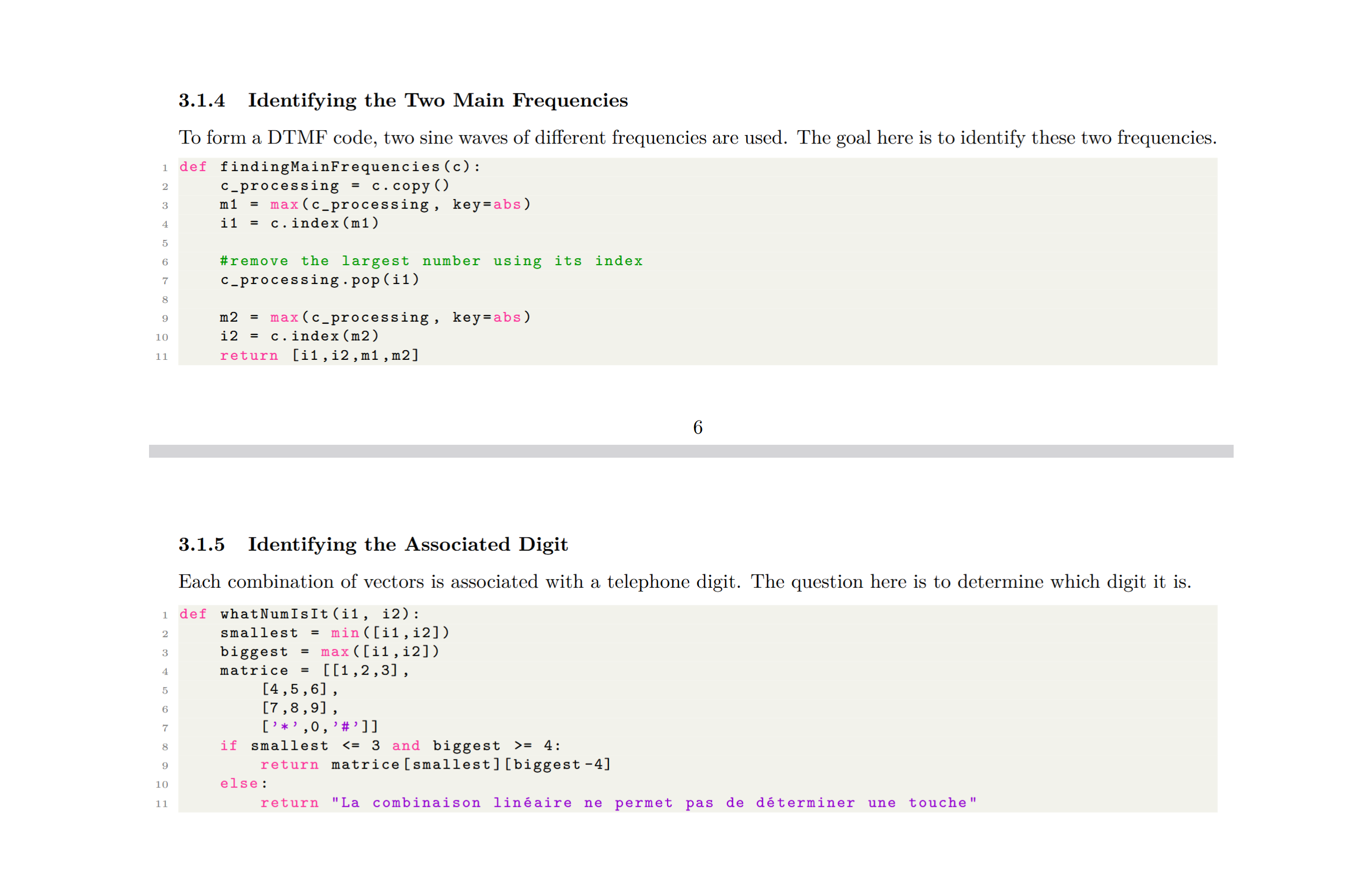
DtmfCodeAnalyzer is an open-source project designed to analyze and filter DTMF (Dual-Tone Multi-Frequency) signals used in conventional telephony. The project provides functionalities to detect and identify keypresses from audio recordings, as well as remove DTMF tones to isolate voice signals.
🎯 Purpose
- 🎵 DTMF Signal Recognition: Identify the key pressed based on the audio recording of its emitted frequencies.
- 🔇 DTMF Noise Removal: Extract and suppress DTMF tones from an audio sample to reveal underlying speech.
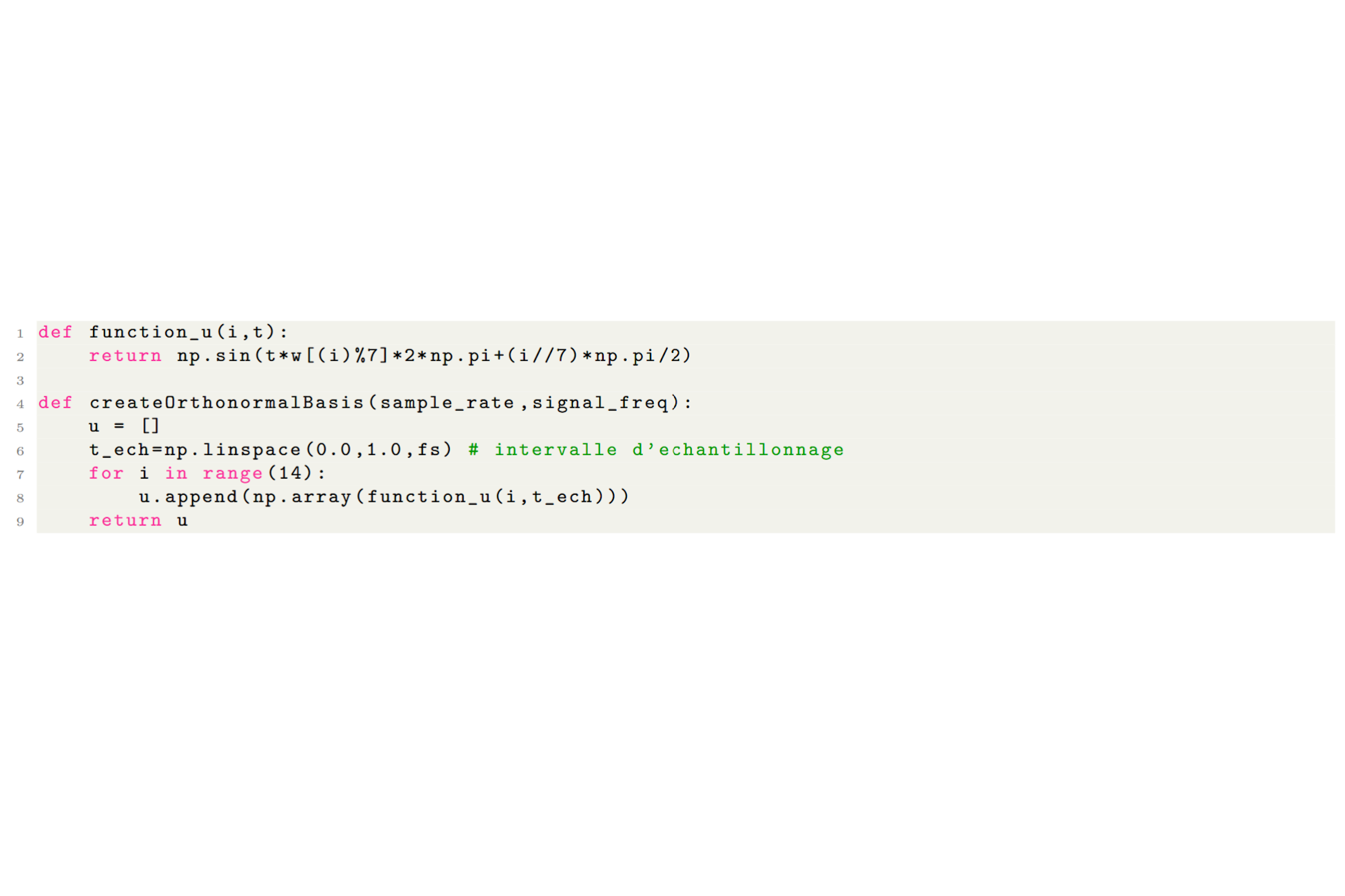
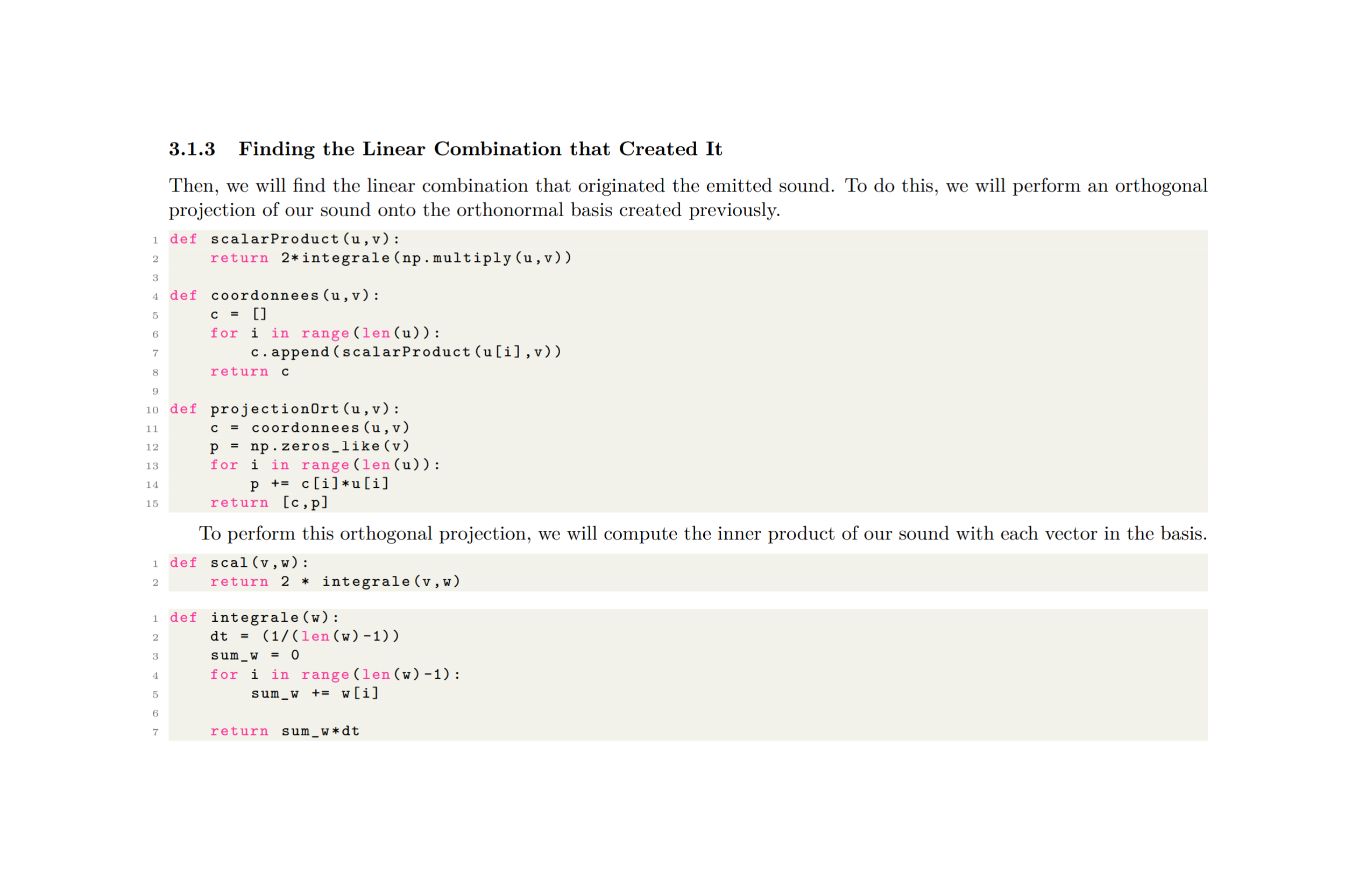
- 📊 Mathematical Approach: Use vector projection in an Euclidean space to determine the closest frequency matches.
📝 Features
| 🏷️ Feature | 🔍 Description |
|---|---|
| 🎛️ DTMF Frequencies | Combination of two distinct tones per key |
| 🎚️ Key Identification | Detects and determines the key pressed |
| 🔊 Noise Filtering | Removes DTMF tones while preserving speech |
| 📉 Mathematical Model | Projects signals into a vector space for analysis |
| 🎤 Audio Processing | Works with recorded audio samples |
| 🖥️ Open-Source | Fully customizable and modifiable |
📐 Signal Processing Approach
| 🎵 Frequency Vector Representation | 🧮 Euclidean Projection | 🎛️ Filtering |
|---|---|---|
 |
 |
 |
MapGenerator
🗺️ France population map makers
Main Project Goal
The main objective of this project is to localize a small number of major cities in France (7–9), chosen so that they are few enough to be easily memorized. The idea is to divide France into 7–9 areas, each dominated by one of these key cities, with the goal that each area contains roughly the same amount of population and wealth. This approach aims to split and rebalance the country’s population and economic activity, which is currently too concentrated in Paris, by promoting a more even distribution across the territory.
MapGenerator is a professional Python tool to generate and export a map of France showing population densities by municipality (commune), using official INSEE and administrative boundaries data.
Features
- Reads French municipality boundaries (JSON) and population data (Excel)
- Handles Paris as a single commune by aggregating arrondissement data if needed
- Computes population density (inhabitants/km²) for each municipality
- Classifies density into 5 custom bins: 0–15, 15–30, 30–50, 50–100, 100+ hab/km²
- Visualizes the map with a professional 5-level red color scale
- Exports the map as a high-resolution PNG with a timestamped filename
Requirements
Install dependencies with:
pip install -r requirements.txt
Example Output
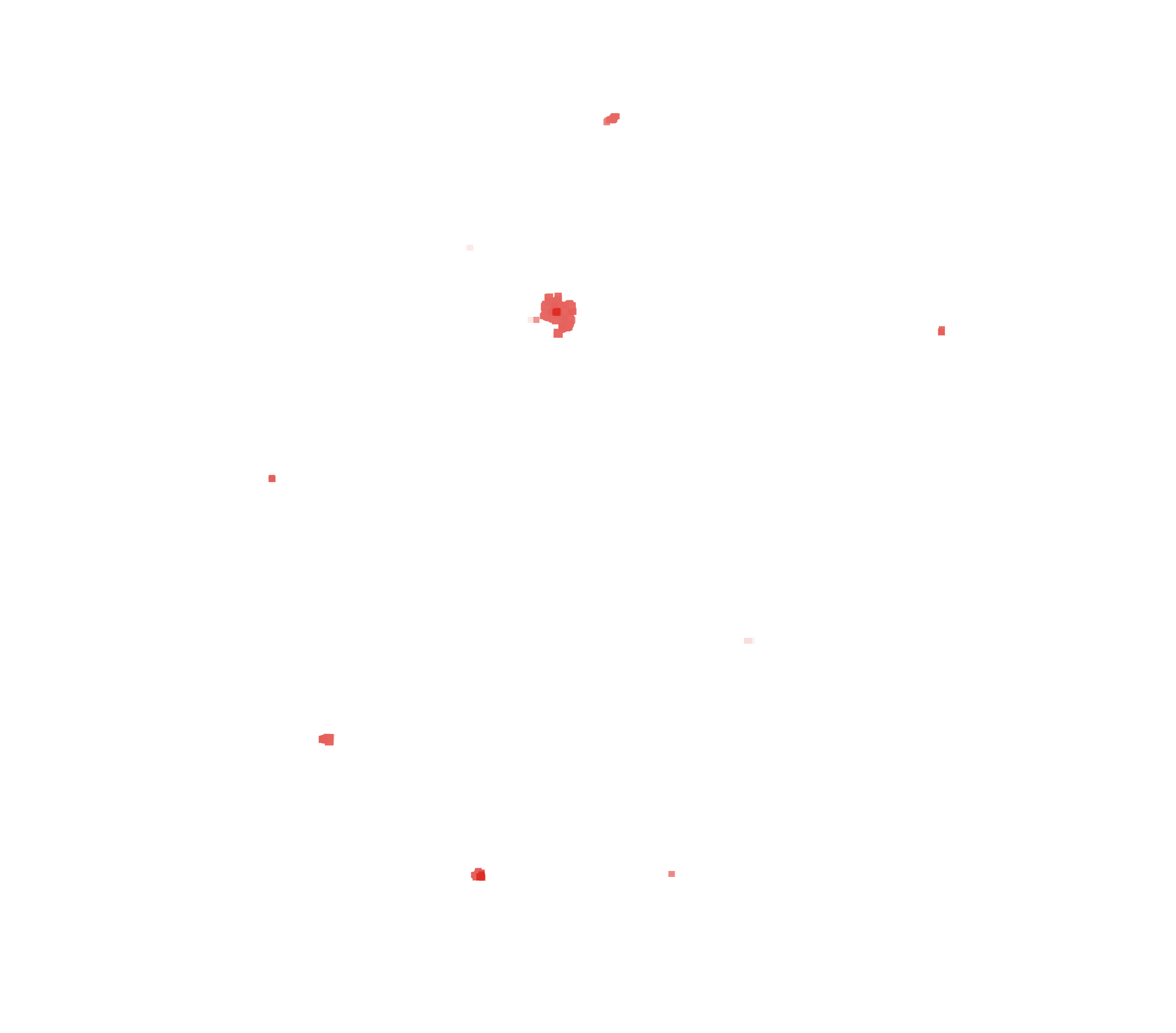
Below is an example of the generated map:
| Population Density Map | Population density threshold map | Repartition map |
|---|---|---|
 |
 |
 |
Usage
- Download the following datasets and place them in the project root:
communes.json(GeoJSON of French municipalities, e.g. from data.gouv.fr)POPULATION_MUNICIPALE_COMMUNES_FRANCE.xlsx(INSEE population by commune, e.g. from insee.fr)
- Run the main script:
python main.py
The map will be displayed and automatically exported as a PNG file (e.g. france_density_map_YYYYMMDD_HHMMSS.png).
Project Structure
main.py— Minimal entry pointmap_generator.py— All core logic, modular and PEP-8 compliantrequirements.txt— Python dependencies
Customization
- You can adjust the density bins or color palette in
map_generator.py. - The export filename is timestamped for easy versioning.
NematodeMorphoAnalyzer
🧬 Nematode morpho analysis tool
NematodeMorphoAnalyzer is an open-source Python project designed to automatically analyze nematode images and extract morphological features such as body length, width, and tail shape. The pipeline applies specific procedures depending on the coiling level (Level 1, Level 2, or Level 3) assigned to each sample.
🎯 Highlights
| 🔍 Feature | 🧾 Description |
|---|---|
| 🧠 Morphological Analysis | Automatically detects morphological features from raw images |
| 🌀 Coiling Level Handling | Applies different analysis routines for each nematode coiling level |
| 📏 Precise Measurements | Calculates length, width, area, tail geometry, and more |
| 🖼️ Image Processing | Uses OpenCV, skimage, PIL, and matplotlib for preprocessing and visualization |
| 📊 Structured Export | Saves results as structured tables using pandas |
⚙️ Workflow Overview
- Image Loading: Reads input images and associated metadata (e.g. coiling level).
- Preprocessing: Inversion, binarization, skeletonization, and morphological cleanup.
- Feature Detection: Measures width, length, area, tail shape, and more.
- Conditional Processing: Applies analysis routines based on coiling level.
- Output & Export: Generates CSV summaries and optionally annotated images.
📁 Project Structure
nematode_morpho_analyzer/
├── data/                     # Input images and metadata
│   ├── level1/
│   ├── level2/
│   └── level3/
├── outputs/                  # Results (CSV files, annotated images)
├── src/                      # Main source code
│   └── main.py               # Main entry point
├── assets/                  # Documentation assets (e.g., images)
│   └── img/
├── requirements.txt         # Python dependencies
└── README.md
🖥️ Sample Output Table
| Image ID | Coiling Level | Length (px) | Avg Width (px) | Tail Shape | Area (px²) |
|---|---|---|---|---|---|
| sample001.png | Level 1 | 435 | 28.5 | tapered | 8120 |
| sample002.png | Level 3 | 310 | 35.2 | rounded | 8904 |
OFDMSystemSim
📡 OFDM system simulation tool
OFDMSystemSim is an open-source project designed to model and simulate an Orthogonal Frequency Division Multiplexing (OFDM) communication system using the Jupyter Notebook environment. The simulation includes transmitter and receiver chains, signal propagation over noisy and multipath channels, synchronization, and advanced analyses such as PAPR and channel equalization.
🎯 Purpose
- 📡 Understand OFDM Communications: Implement the full digital chain from symbol generation to reception.
- 🧪 Numerical Experimentation: Analyze the effects of noise, multipath, and timing offsets.
- 📊 Performance Evaluation: Compute BER, visualize spectra, histograms, and constellations.
- ⚙️ Algorithm Exploration: Implement oversampling, hard-clipping, synchronization techniques, etc.
- 🛠️ Educational & Reusable: A versatile base for signal processing students, researchers, or enthusiasts.
📝 Features
| 🏷️ Feature | 🔍 Description |
|---|---|
| ⚙️ Fully Parametric Setup | Modulation type (QAM/PSK), SNR, number of subcarriers, symbol duration |
| 💾 OFDM Signal Generation | IFFT processing, cyclic prefix insertion, signal vector construction |
| 🌊 AWGN Channel | Additive white Gaussian noise based on specified SNR |
| 🛰️ Multipath Channel | Impulse response modeling and convolution with variable echo amplitudes |
| 🎛️ Timing Synchronization | Simulate timing offsets and evaluate simple synchronization strategies |
| 📉 PAPR Analysis | CCDF evaluation and visualization of PAPR distributions |
| ✂️ Hard Clipping | Reduce PAPR using nonlinear clipping with tunable thresholds |
| 📶 Zero-Forcing Equalization | Simple frequency-domain channel equalization |
| 📈 Visual Outputs | Constellations, histograms, power spectral density, PAPR curves |
🖥️ Screenshots
| 📡 OFDM Signal | 📊 Histograms | 📶 Constellation |
|---|---|---|
 |
 |
 |
🧪 Included Experiments
- BER vs SNR evaluation for QAM-16 and PSK-16
- Multipath channel simulation with variable echo amplitudes
- Desynchronization effects and their impact on BER and constellations
- PAPR CCDF analysis for various FFT sizes (32–1024)
- Hard clipping PAPR reduction (2 dB to 10 dB thresholds)
- Zero-forcing channel equalization
🛠️ Tools & Requirements
- 🧠 Python 3.8+
- 📦 Libraries:
numpy,scipy,matplotlib,notebook - 💻 Platform: Jupyter Notebook (local or online)
NucleoF411RE-ApplicationShield
🎛️ Nucleo F411RE synth project!
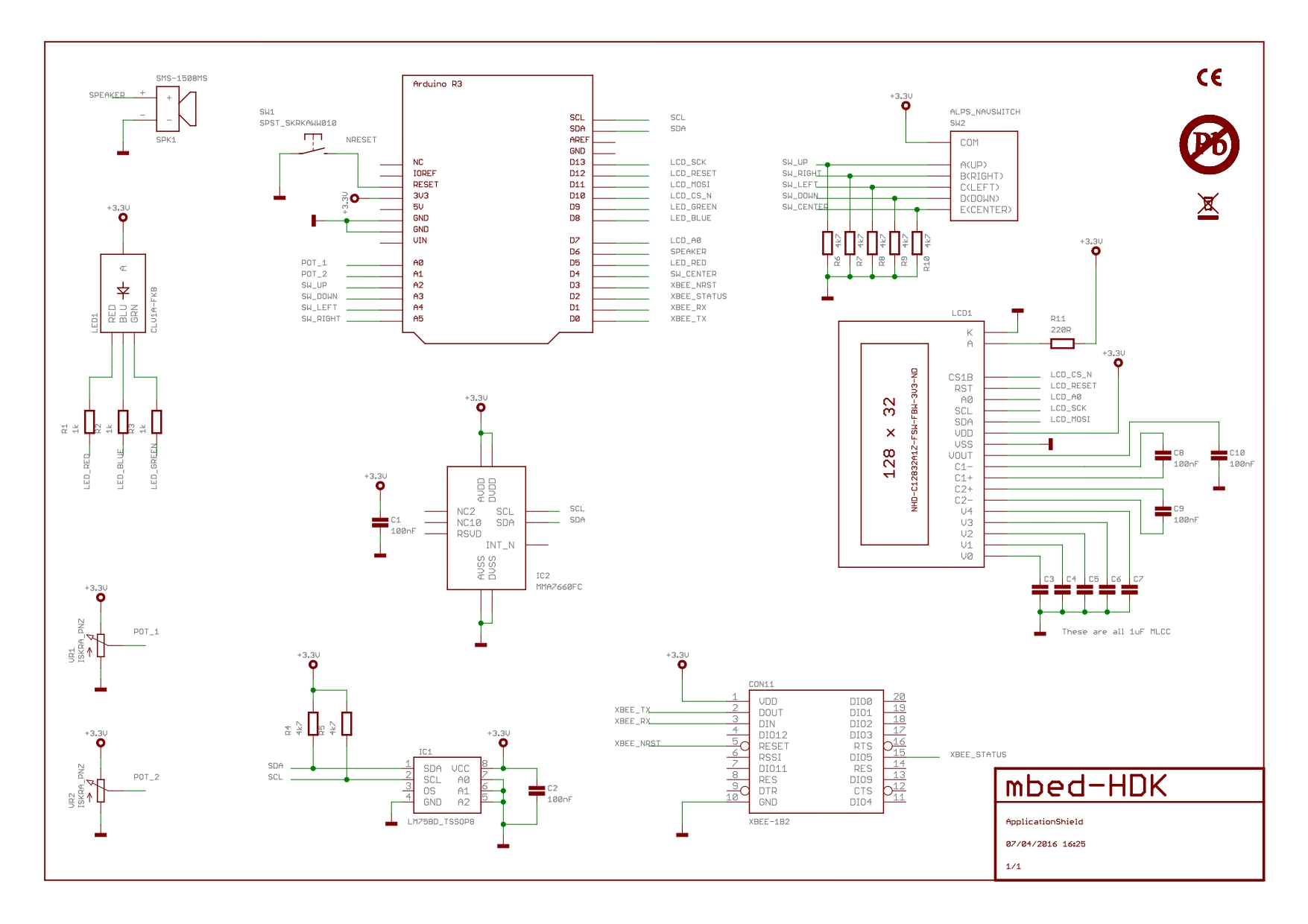
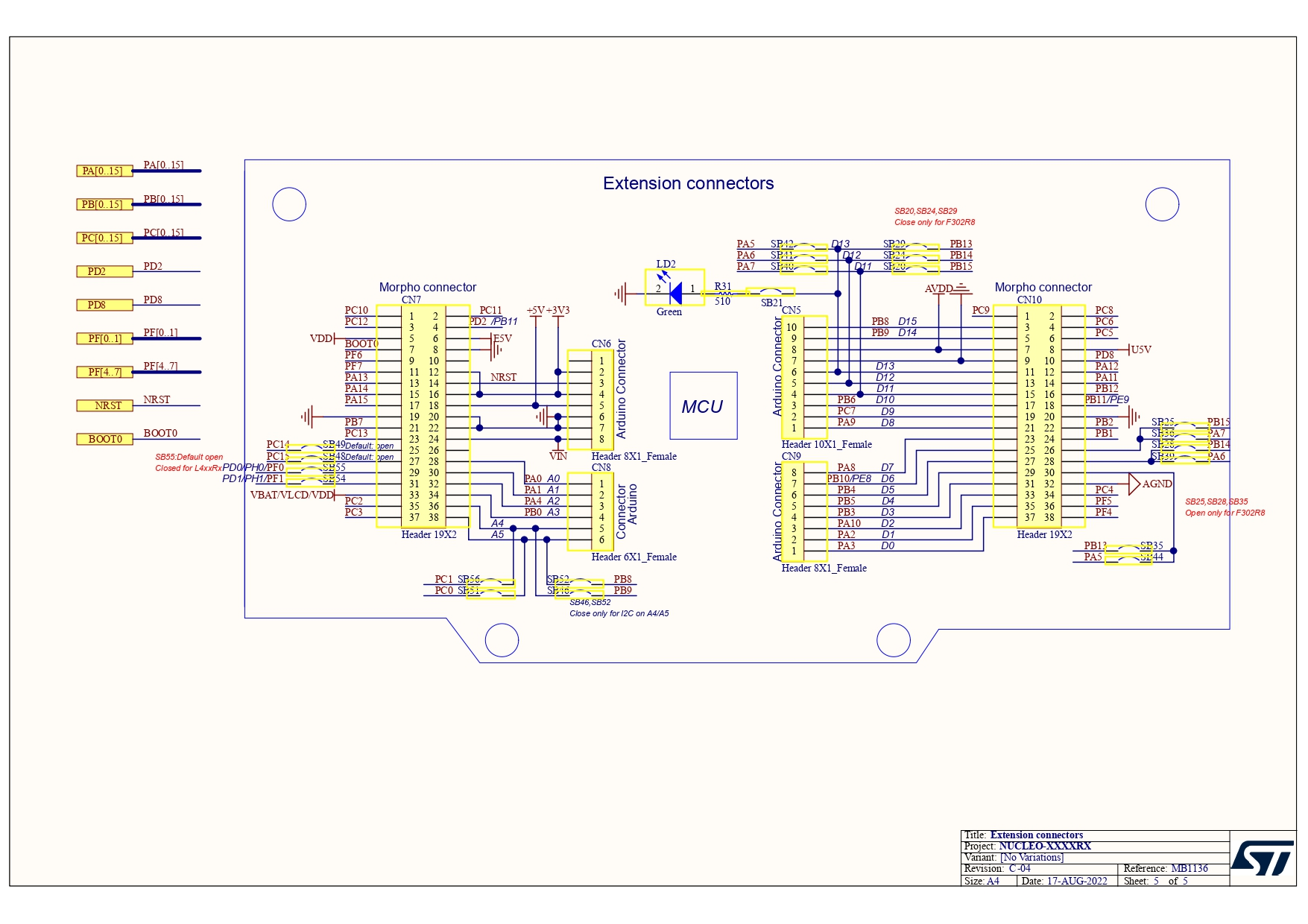
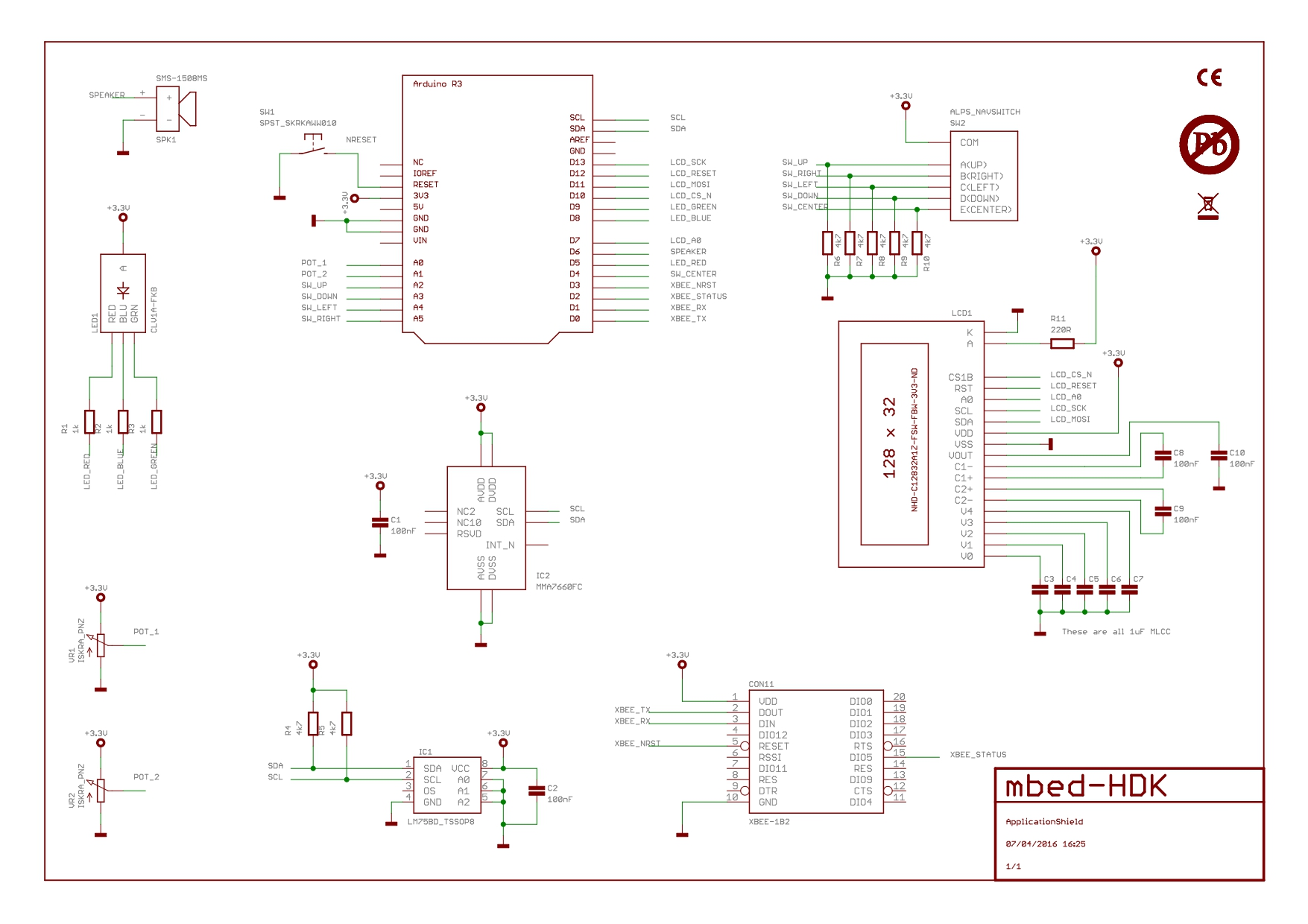
NucleoF411RE-ApplicationShield is an open-source firmware project designed to leverage the Nucleo-F411RE development board in conjunction with the Application Shield from ARMmbed. This project explores all the functionalities offered by the combination of the Nucleo-F411RE and the Application Shield, providing a comprehensive codebase for testing and demonstrating the capabilities of the microcontroller.
🎯 Purpose
- 🔌 GPIO Control: Interact with GPIO pins for reading, writing values, and generating PWM signals.
- ⏱️ Timer Management: Utilize timers to detect short and long button presses.
- ⚡ Interrupt Handling: Implement timer and button press interrupts for dynamic LED control.
- 💬 Serial Communication: Facilitate communication between the computer and the Nucleo board.
- 🌡️ Sensor Interaction: Communicate via I2C and SPI to gather data from sensors and control displays.
- 🔄 ADC Utilization: Read analog values from potentiometers.
📝 Features
| 🏷️ Feature | 🔍 Description |
|---|---|
| 💡 GPIO Control | Read/write values and generate PWM signals. |
| ⏲️ Timer Management | Manage timers TIM2 to TIM5 for button presses. |
| ⚠️ Interrupts | Use interrupts for LED blinking and button actions. |
| 💻 Serial Communication | Communicate with the Nucleo board via serial. |
| 🌡️ I2C Communication | Retrieve temperature from the LM75 sensor and interact with MMA7660 accelerometer. |
| 📺 SPI Communication | Control an LCD display using SPI. |
| 🎚️ ADC Usage | Read potentiometer angles through ADC. |
ApplicationShield Schematic
Nucleo-F411RE Extension Schematic
🎛️ Example Applications
1. PWM via LED
Utilize PWM (Pulse Width Modulation) to control the brightness of an LED. By adjusting the duty cycle, the LED can be dimmed or brightened, allowing for various visual effects. This is particularly useful for applications such as light dimming or motor speed control.
2. GPIO Input via Joystick
Use the GPIO to read the logical levels from the joystick. The program update outputs such as LEDs based on the current status of the joystick buttons.
3. ADC Potentiometer Reading
Use the ADC (Analog-to-Digital Converter) to read values from a potentiometer. These values can then be used to control parameters such as the brightness of an LED through PWM (Pulse-Width Modulation), allowing the LED intensity to vary according to the potentiometer’s position.
4. PWM via Speaker
Utilize PWM (Pulse Width Modulation) to generate sounds via a speaker. By varying the frequency, not the duty cycle, different tones can be produced. The duty cycle remains constant while frequency changes create distinct audible notes. This method is commonly used for sound generation and simple audio signals.”
5. Serial Communication
Establish serial communication between the Nucleo-F411RE and a PC for data exchange. This can be used for debugging, sending sensor readings, or receiving commands from the computer.
6. I2C Temperature Reading
Use the I2C protocol to communicate with temperature sensors such as the LM75. This data can then be used for environmental monitoring or to trigger actions based on temperature thresholds.
7. SPI LCD Control
Use the SPI protocol to control an LCD display. This application could display system status, sensor readings, or any other relevant information on a small screen.
📜 Code Structure
📁 NucleoF411RE-ApplicationShield/
├── 📂 Core/
│   ├── main.c        # Main firmware loop
│   ├── gpio.c        # GPIO handling and PWM
│   ├── timers.c      # Timer management
│   ├── interrupts.c  # Interrupt handling
│   ├── serial.c      # Serial communication control
│   ├── i2c.c         # I2C communication
│   ├── spi.c         # SPI communication for LCD
│   ├── adc.c         # ADC handling
├── 📂 Drivers/        # Nucleo HAL libraries
├── 📂 Inc/           # Header files
├── 📂 Assets/        # UI elements, example configurations
└── README.md         # This file
SmartRadioAlarm
🎧 ESP32 WiFi radio, BT speaker & alarm clock
SmartRadioAlarm is an open-source project that integrates Internet Radio, Bluetooth audio playback, and a programmable alarm into a single device. Users can control it via physical buttons on the device or through a cross-platform Flutter app connected over the local network.
🎯 Purpose
- 🎵 Audio Streaming: Stream music from Internet radio or Bluetooth devices.
- ⏰ Alarm Functionality: Schedule alarms with custom audio streams.
- 🔘 User Control: Easily adjust volume, play/pause, and stop using physical buttons.
- 🌐 Network Configuration: Configure the device via Wi-Fi and control it using a REST API.
- 🛠️ Open-source & Customizable: Modify and extend for various audio or alarm use cases.
📝 Features
| 🏷️ Feature | 🔍 Description |
|---|---|
| 🎶 Internet Radio | Stream music from online sources |
| 📱 Bluetooth A2DP Sink | Play audio from smartphones or other BT devices |
| 🔊 Volume & Playback Control | Control volume and playback via buttons or mobile app |
| ⏰ Programmable Alarm | Set alarm time and choose a custom audio stream |
| 🌐 REST API | Local API for configuration and real-time control |
| 🖥️ ESP32 + I2S DAC | High-quality audio output through DAC (PCM5102, MAX98357A, etc.) |
| 🌍 Cross-platform App | Flutter app compatible with both Android & iOS |
⚡ Quick Setup
-
Clone the repository:
git clone https://github.com/mpek29/SmartRadioAlarm.git cd SmartRadioAlarm -
Set the ESP32 target:
idf.py set-target esp32 -
Build, flash, and monitor:
idf.py build flash monitor
📚 Full Documentation
For detailed architecture, schematics, API reference, and configuration instructions, see the /docs folder.
UnoD1R32-ApplicationShield
🎛️ ESP32 Application Shield demo!
UNO-D1-R32-ApplicationShield is an open-source firmware project based on ESP-IDF, designed to run on the UNO D1 R32 Board Module (ESP32) with the ARMmbed Application Shield. This project demonstrates the ESP32’s capabilities with practical examples using GPIO, ADC, PWM, I2C, SPI, and UART for embedded applications.
🎯 Purpose
- 🔌 GPIO Control: Read/write digital pins and generate PWM signals using LEDC.
- ⏱️ Timer Management: Use hardware/software timers to detect button presses.
- ⚡ Interrupt Handling: React to button or GPIO events using interrupts.
- 💬 UART Communication: Exchange data with a PC via UART for debugging or control.
- 🌡️ Sensor Interaction: Use I2C/SPI to read sensors and control external devices.
- 🔄 ADC Utilization: Read analog input values such as potentiometer voltage.
📝 Features
| Feature | Description |
|---|---|
| 💡 GPIO + PWM | Use gpio and ledc drivers for digital and PWM control. |
| ⏲️ Timer Support | Use esp_timer or hardware timers for time-based events. |
| ⚠️ GPIO Interrupts | Use gpio_install_isr_service for handling input events. |
| 💻 UART Communication | Full duplex serial with uart_driver_install(). |
| 🌡️ I2C Sensors | Read LM75 temp sensor, MMA7660 accelerometer via I2C. |
| 📺 SPI LCD | Display sensor or system data using SPI LCD. |
| 🎚️ ADC Readings | Use adc1_get_raw() with calibration for accurate values. |
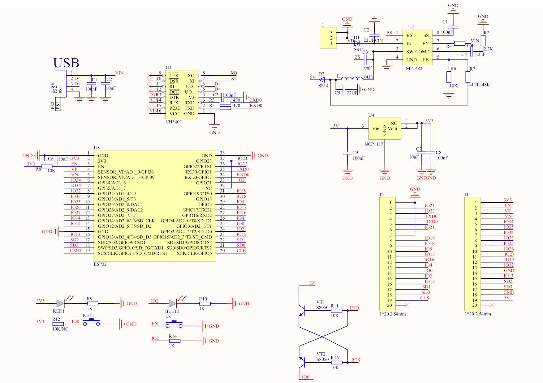
🔌 Application Shield Schematics
🧭 UNO D1 R32 Pinout
🎛️ Example Applications
1. PWM via LED
Utilize PWM (Pulse Width Modulation) to control the brightness of an LED. By adjusting the duty cycle, the LED can be dimmed or brightened, allowing for various visual effects. This is particularly useful for applications such as light dimming or motor speed control.
2. GPIO Input via Joystick
Use the GPIO to read the logical levels from the joystick. The program update outputs such as LEDs based on the current status of the joystick buttons.
3. ADC Potentiometer Reading
Use the ADC (Analog-to-Digital Converter) to read values from a potentiometer. These values can then be used to control parameters such as the brightness of an LED through PWM (Pulse-Width Modulation), allowing the LED intensity to vary according to the potentiometer’s position.
4. PWM via Speaker
Utilize PWM (Pulse Width Modulation) to generate sounds via a speaker. By varying the frequency, not the duty cycle, different tones can be produced. The duty cycle remains constant while frequency changes create distinct audible notes. This method is commonly used for sound generation and simple audio signals.”
5. Serial Communication
Establish serial communication between the UnoD1R32 and a PC for data exchange. This can be used for debugging, sending sensor readings, or receiving commands from the computer.
6. I2C Temperature Reading
Use the I2C protocol to communicate with temperature sensors such as the LM75. This data can then be used for environmental monitoring or to trigger actions based on temperature thresholds.
7. SPI LCD Control
Use the SPI protocol to control an LCD display. This application could display system status, sensor readings, or any other relevant information on a small screen.
📁 Code Structure
uno-d1-r32-appshield/
├── main/
│ ├── main.c # Main firmware entry point
│ ├── gpio_ctrl.c # GPIO and PWM control logic
│ ├── adc_ctrl.c # Analog input handling
│ ├── timer_ctrl.c # Software/hardware timer handling
│ ├── uart_comm.c # UART interface
│ ├── i2c_ctrl.c # I2C communication
│ ├── spi_display.c # LCD SPI control
│ └── include/ # Header files
├── components/ # Optional external libs
├── assets/ # Images, config files, schematics
├── CMakeLists.txt
└── README.md
AntUpRising
Global Game Jam 2023
AntUpRising is an engaging 2D platformer created during the Global Game Jam 2023. Step into the shoes of an ant and dive into a vibrant world where your mission is to bring food back to the queen ant. But beware! Strange roots have taken over the anthill, causing the ants to become aggressive and unpredictable.
🎯 Purpose
- 🍽️ Food Retrieval: Collect resources to nourish the queen ant.
- ⚔️ Avoid Threats: Dodge the crazed ants and other dangers along your journey.
- 👑 Reach the Queen: Overcome obstacles to make your way to the queen’s chamber.
📝 Features
- 🌍 Vibrant 2D Environment: Immerse yourself in a colorful and detailed world.
- 🏃 Dynamic Gameplay Mechanics: Interact with enemies and tackle various challenges.
- 🎮 Immersive Gaming Experience: Enjoy an exciting adventure through the tunnels of the anthill.
👥 Team Members
- Mael Madec
- Florian Pasco
- Romain Cloâtre
- Théo De Morais
- Romain Fauvel
BoardMapper
🛠️ PCB placement map generator
BoardMapper is an open-source tool designed to automatically generate PCB layout. It labels component references (e.g. U1, R1, C1) directly on the circuit image, facilitating component identification for reverse engineering purposes.
🎯 Purpose
- 🤖 Automation: Eliminates the need for manual placement annotation on PCB layouts.
- ⏱️ Efficiency: Saves time for engineers and makers working on PCB assembly and debugging.
- 🔍 Clarity: Provides a clear visual reference for debugging, testing, and manufacturing.
- 💻 Cross-Platform: Works on Windows, Linux, and macOS systems.
📝 Annotation
| Position | Original | Annotated |
|---|---|---|
| Top | 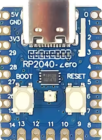 |
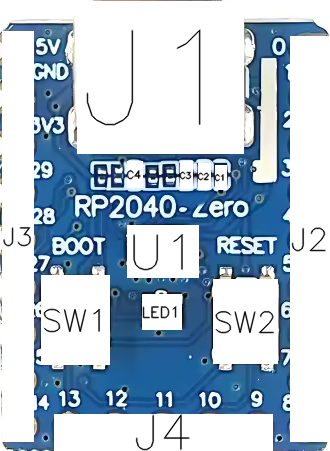 |
| Bottom | 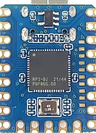 |
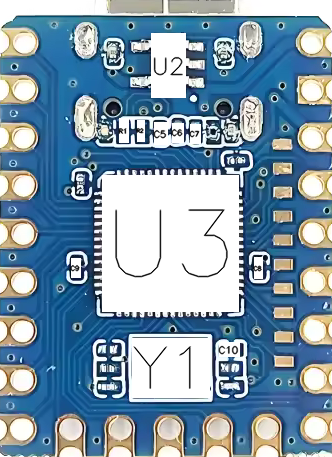 |
📋 Requirements
- Python: Version 3.6 or higher
- Required Libraries:
opencv-python(for image processing)lxml(for XML parsing)
🚀 Installation Instructions
🛠️ Setup
-
Clone the repository or Download the project to your local machine.
- Labeling the PCB:
- Step 1: Take a photo of both the top and bottom layers of the chosen PCB.
- Step 2: Place the
top.pngandbottom.pngimages into theinputfolder. - Step 3: Install the latest version of LabelImg.
- Step 4: Open
top.pngin LabelImg and draw bounding boxes around each component. Label each component according to its type:- R: Resistor
- C: Capacitor
- L: Inductor
- F: Fuse
- POT: Potentiometer
- D: Diode
- LED: LED
- Q: Transistor (BJT, MOSFET)
- U: Integrated Circuit (IC)
- J: Connector
- K: Relay
- SW: Switch
- Y: Quartz / Resonator
- SP: Speaker
- ANT: Antenna
- BUZ: Buzzer
LabelImg Shortcuts:
- ✏️ W: Draw a new rectangular bounding box (RectBox)
- ❌ D: Delete the last drawn bounding box
- 💾 Ctrl + S: Save the annotation as an XML file
- ⏪ Ctrl + Z: Undo the last action
- 📋 Ctrl + C: Copy a bounding box
- 📏 Ctrl + V: Paste a copied bounding box
- 🔍 Ctrl + A: Select all bounding boxes
- 🔄 Ctrl + R: Rotate the image (for better labeling)
- 🚫 Esc: Cancel the current operation or close a dialog box
- Step 5: After labeling the
top.png, save the annotation astop.xml. - Step 6: Repeat the labeling process for the
bottom.pngand save it asbottom.xml. - Step 7: Place both
top.xmlandbottom.xmlinto theinputfolder.
- Running the Tool:
- Windows: Double-click on
setup_and_run.batto automatically run the script. The tool will read the XML annotations, draw bounding boxes on the images, and save the annotated images. - Linux/macOS: You can run the script from the terminal:
chmod +x script.sh
./script.sh
- Windows: Double-click on
- 📂 Output:
- After the script has executed, navigate to the
outputfolder to find the resulting annotated images:top_annotated.pngbottom_annotated.png
- After the script has executed, navigate to the
🤝 Contributions
If you’d like to contribute to the project, please follow these steps:
- Fork the repository
- Create a feature branch
- Commit your changes
- Push to the branch
- Open a pull request
We welcome any contributions to improve BoardMapper! 🎉
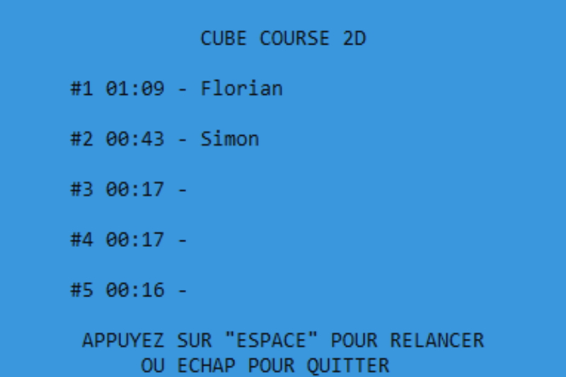
CubeCourse2D
🕹️ Fast-paced random platformer!

CubeCourse2D is a fast-paced platformer where the player must survive as long as possible by jumping from platform to platform. But be careful—platforms are generated randomly, making each game unique and unpredictable!
🎯 Objective
- 🏃 Survival: Stay alive by jumping across platforms.
- ⚠️ Random Challenges: Platforms and enemies appear randomly, keeping you on your toes.
- 🏆 Competition: Test your reflexes and beat your high scores!
📝 Features
- 🎨 Minimalist Design: A simple yet effective aesthetic for full immersion.
- 🎲 Random Generation: No two levels are the same—every run is a new challenge!
- ⚔️ Enemy Elimination: Jump on enemies to defeat them, but be careful not to miss!
- 🎶 Inspired by Geometry Dash: A fast-paced and addictive gameplay experience.
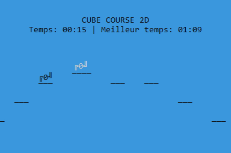
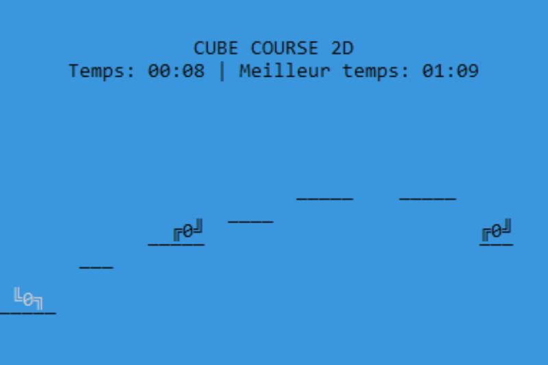
📷 Screenshots
FlutterIoTManager
📱 Manage your IoT devices easily
FlutterIoTManager is a cross-platform Flutter application designed to manage multiple IoT devices. Users can add devices, navigate their profiles, switch between operational states, and configure associated parameters remotely over a local network or cloud connection.
🎯 Purpose
- 📱 Multi-Device Control: Manage multiple IoT devices from a single app.
- 🔄 State Navigation: Switch between device modes or operational states.
- ⚙️ Parameter Configuration: Set and adjust device-specific parameters.
- 🌐 Network Connectivity: Connect devices over Wi-Fi or cloud.
- 🛠️ Open-source & Extensible: Add support for new devices easily.
📝 Features
| 🏷️ Feature | 🔍 Description |
|---|---|
| ➕ Device Discovery & Adding | Detect and add new IoT devices to the app |
| 📂 Device Profiles | View and manage individual device settings |
| 🔄 State Management | Switch between operational states (e.g., Radio, Bluetooth, Alarm) |
| ⚙️ Parameter Configuration | Adjust volume, schedule alarms, select streams, and other device-specific settings |
| 🌐 Network & Cloud Integration | Control devices locally or remotely through cloud services |
| 🌍 Cross-platform | Works on Android and iOS devices |
📷 Screenshots
| Device List | Product | Settings |
|---|---|---|
 |
 |
 |
MiniMusicSoftware
🎼 Mini computer music software
MiniMusicSoftware is an open-source mini computer music software package designed to facilitate the understanding of both software development best practices and data lifecycle in digital music processing.
🎯 Purpose
- 🎼 Music Generation: Convert a JSON-formatted score into an audible musical piece.
- 📖 Professional Development Practices: Encourage consulting documentation, using code analyzers, testing code, and writing documentation.
- 🔄 Data Lifecycle Understanding: Explore how data is created, manipulated, copied, accessed, and destroyed in a program.
📝 Features
| 🏷️ Feature | 🔍 Description |
|---|---|
| 🎶 Input Format | JSON-based musical score |
| 🎵 Output Format | Generated music from JSON |
| 🎹 MIDI Support | Partial (final phase not fully completed) |
| 🔍 Code Analysis | Emphasizes best coding practices |
| 🛠️ Testing | Promotes unit testing for reliability |
| 📖 Documentation | Encourages well-documented code for maintainability |
📁 Project Structure
MiniMusicSoftware/
├── Cargo.lock
├── Cargo.toml
├── README.md
├── structure.txt
├── assets/                    # Documentation images
│   └── img/
│       └── main.png
├── file/                      # Musical data files
│   ├── json/
│   │   ├── Child_In_Time.json
│   │   ├── instruments.json
│   │   └── Isnt_she_lovely.json
│   ├── mid/
│   │   └── Isnt_she_lovely.mid
│   └── wav/
│       ├── audio.wav
│       ├── Child_In_Time.wav
│       ├── organ.wav
│       ├── save_wav_test.wav
│       ├── sound_track_test.wav
│       └── test.wav
├── src/                       # Core source code
│   ├── instrument.rs
│   ├── lib.rs
│   ├── main.rs
│   ├── note.rs
│   └── sound_track.rs
├── tests/                     # Integration tests
│   └── integration.rs
└── target/                    # Build output (generated by Cargo)
VATN-WaterGame
💧 A strategic game on water management!
VATN (from the Old Norse word for “water”) is a game designed to raise awareness about water management. Players must make critical daily decisions to address major water-related issues in their country, influencing key parameters that determine the nation’s survival.
🎯 Purpose
- 💧 Water Management Awareness: Educate players on the importance of sustainable water policies.
- 🎮 Engaging Decision-Making: Every day presents a new challenge that affects the nation’s status.
- 🏆 Survival & Strategy: Keep your country alive as long as possible by maintaining stability.
- 📊 Progress Tracking: Visualize the evolution of key parameters through in-game graphs.
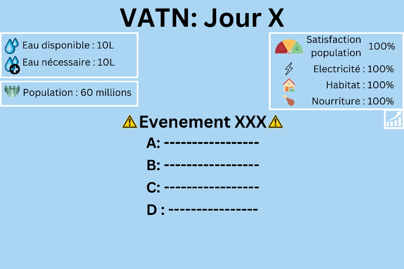
📝 Features
| 🏷️ Feature | 🔍 Description |
|---|---|
| 🌎 Game Type | Strategic Decision-Making Simulation |
| 📅 Daily Choices | Players make decisions each day affecting country parameters |
| 📉 Dynamic Statistics | Key indicators fluctuate based on player actions |
| 💀 Game Over | The country collapses if the population reaches 0 |
| 📂 Save & Load | Resume previous games using saved files |
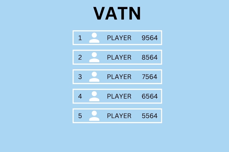
| 🏅 Rankings | Compare results with previous local games |
| 📊 Graphical Summary | Track country status evolution over time |
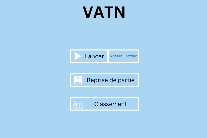
📺 Gameplay Overview
| 🎮 Main Menu | 📊 In-Game Statistics | 🏆 Endgame Rankings |
|---|---|---|
 |
 |
 |
WorldTourRidersDatabase
🚴♂️ SQLite database for pro cyclists
WorldTourRidersDatabase is an SQLite-based project designed to manage professional cyclists and their teams affiliated with the International Cycling Union (UCI). The database enables structured data storage, querying, and management of riders and their associations with World Tour teams.
🎯 Purpose
- 📂 Data Storage: Efficiently store and manage rider information within an SQLite database.
- 🔍 Advanced Queries: Utilize SQL queries to retrieve, filter, and analyze cycling-related data.
- 🔗 Table Associations: Implement relational connections between riders, teams, and relevant cycling entities.
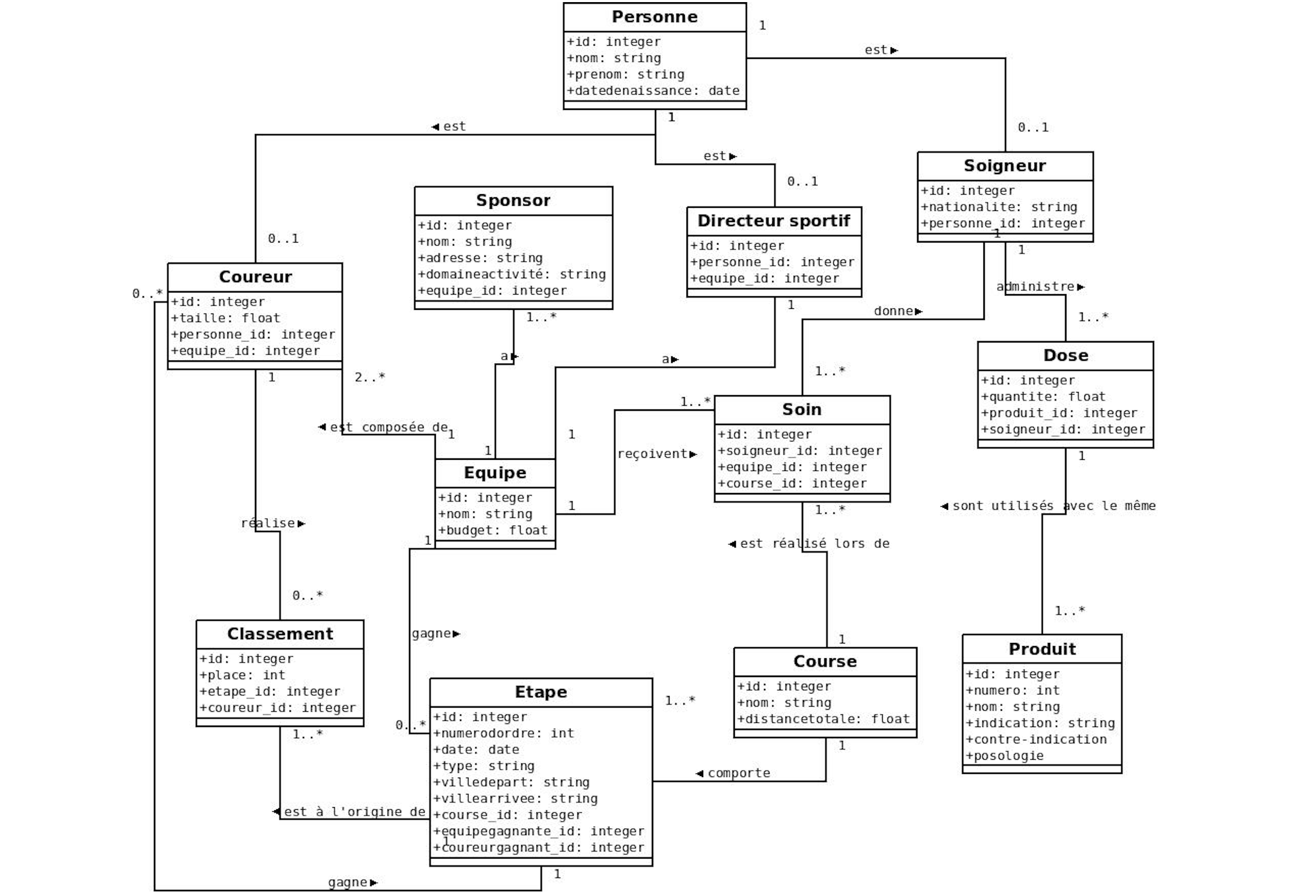
- 📊 UML Modeling: Design and visualize the database schema using UML modeling techniques.
📝 Features
| 🏷️ Feature | 🔍 Description |
|---|---|
| 📌 Rider Management | Store and organize details about professional cyclists |
| 🏆 Team Associations | Link riders to their respective World Tour teams |
| 🔍 SQL Queries | Perform complex queries to extract meaningful insights |
| 📊 Database Normalization | Ensure efficient and scalable data structure |
| 🖥️ SQLite Integration | Fully functional within an SQLite environment |
| 📜 UML Diagrams | Visualize table relationships for better understanding |
📐 Database Structure & Design
ZEthyDex
📱 Android app like a Pokédex
An open-source application designed in the style of a Pokédex, allowing users to explore and catalog various creatures and features. This project aims to provide a fun and interactive way to engage with the Pokémon universe.
🎯 Purpose
- 📚 Cataloging: Create an extensive database of creatures with detailed information.
- 🎮 Interactive Experience: Offer a user-friendly interface for exploration.
- 🛠️ Open Source Development: Encourage collaboration and contributions from developers.
📝 Features
- 🌟 User-Friendly Interface: Easy navigation and search functionalities.
- 🔍 Search Functionality: Quickly find information on specific creatures.
- 📸 Image Gallery: Visual representation of each creature.
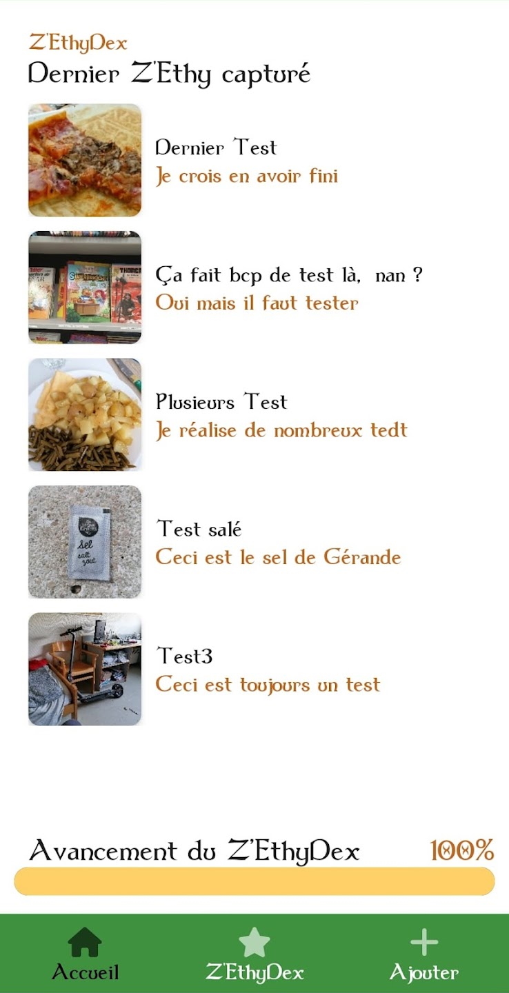
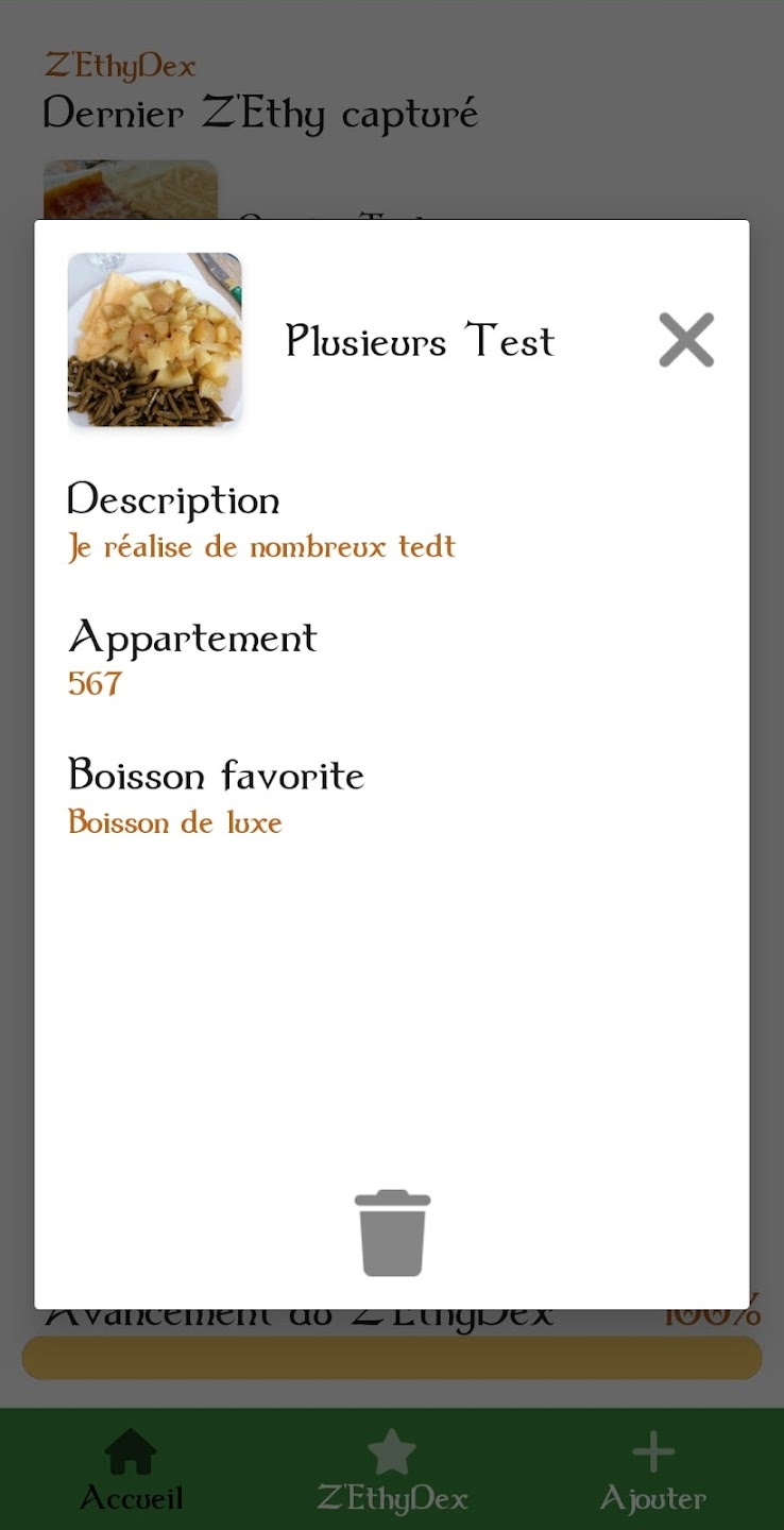
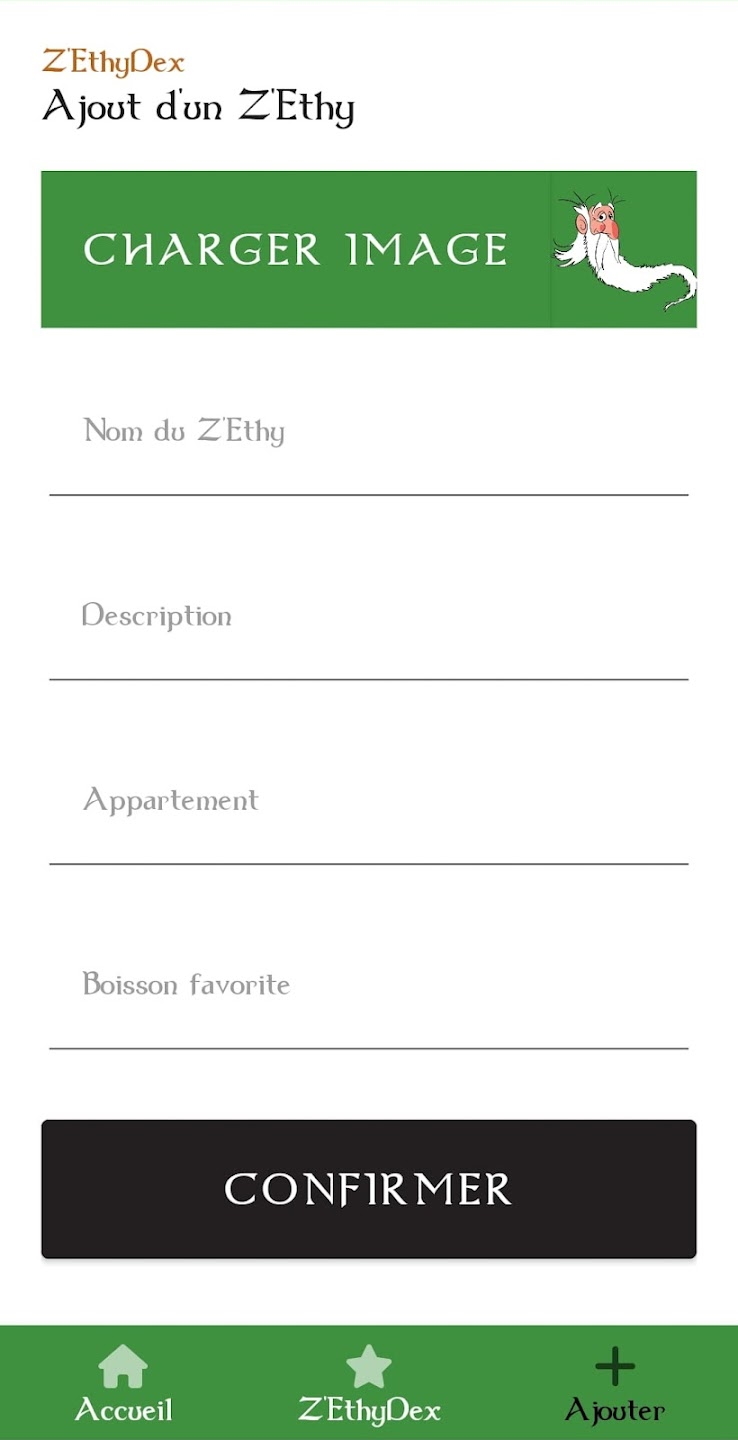
📷 Screenshots
learning
🌐 Jekyll site to archive my knowledge
An open-source website created using Jekyll and the “al-folio” theme, designed to archive my learning journey and share knowledge with anyone interested. This project serves as a personal portfolio and a resource hub.
🎯 Purpose
- 📖 Knowledge Sharing: Documenting and sharing what I’ve learned.
- 🌐 Personal Portfolio: Showcasing projects and skills.
- 🛠️ Open Source Development: Encouraging contributions and feedback from the community.
🌟 Features
- 📄 Responsive Design: Optimized for various devices.
- 🔍 Search Functionality: Easily find content and resources.
- 🛠️ Customization Options: Adapt the site to your preferences.
mpek29-latex-template
📄 Simple LaTeX template for ENIB
A beautiful, simple, and clean LaTeX template designed for ENIB students who want to write project reports. If you like the template, feel free to give it a star!
🎯 Purpose
- ✍️ Streamlined Reporting: Facilitate the creation of professional-looking project reports.
- 🎓 Student Resource: Tailored specifically for ENIB students’ needs.
- 🛠️ Open Source Development: Encourage collaboration and customization from users.
📝 Getting Started
To use this template, I recommend following this tutorial.
After that, simply write your LaTeX code in the body.tex file.